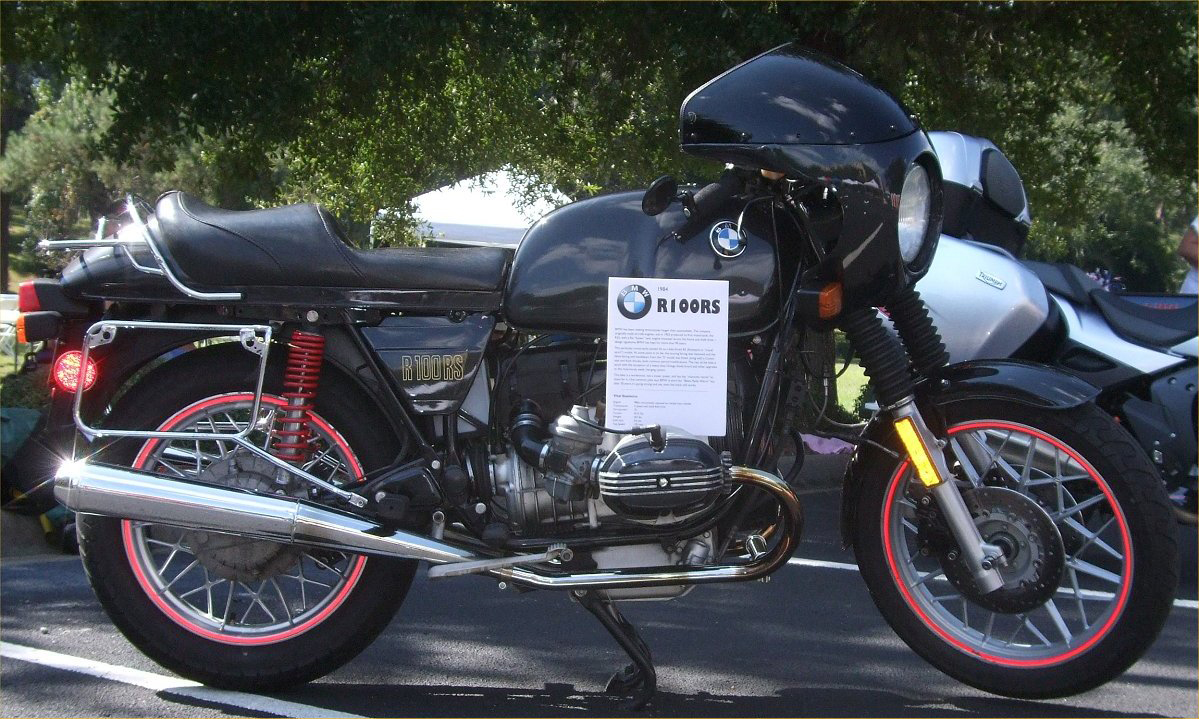
Resurrecting an Airhead from the ashes of misfortune
Coming home from dinner one night, I on my airhead and Gill on her Ninja, I noticed a puff of white
from behind the fairing as I approached a red light. As we pulled to a stop, I heard her yelling "You're on fire!"
That was instantly apparent from the smoke that came billowing out
when we came to a standstill. I got the bike to the side of the road,
hit the kill switch, turned the key off and stepped away. I could see an
orange glow inside the headlight bucket but there were no open flames,
so I popped the seat off and removed the gas tank. Fortunately, the tank
is only held on by two thumbscrews, so the whole enterprise took maybe 20
seconds. I noticed the headlight was still on, so I grabbed a wrench,
disconnected the battery and waited.
Eventually the smoke died down and there was no further sign of fire.
When we got the bike back to the garage, I could see burnt wiring under
the fairing. That weekend, the teardown started and the prognosis was
not good.
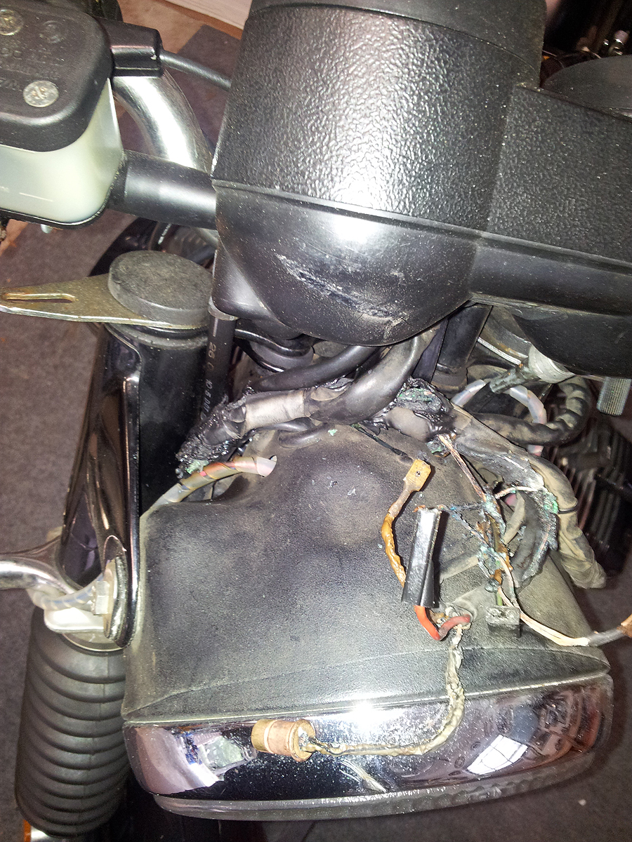
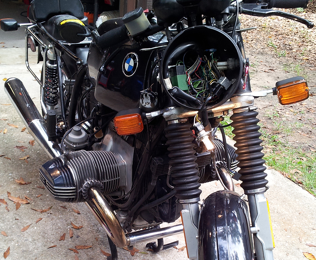
With the fairing off, you could see that all of the wiring that went
to the voltmeter and clock had overheated. With the handlebars,
instruments and switchgear removed, it looked even worse. What hadn't
cooked outright was still damaged by contact with hot wiring.
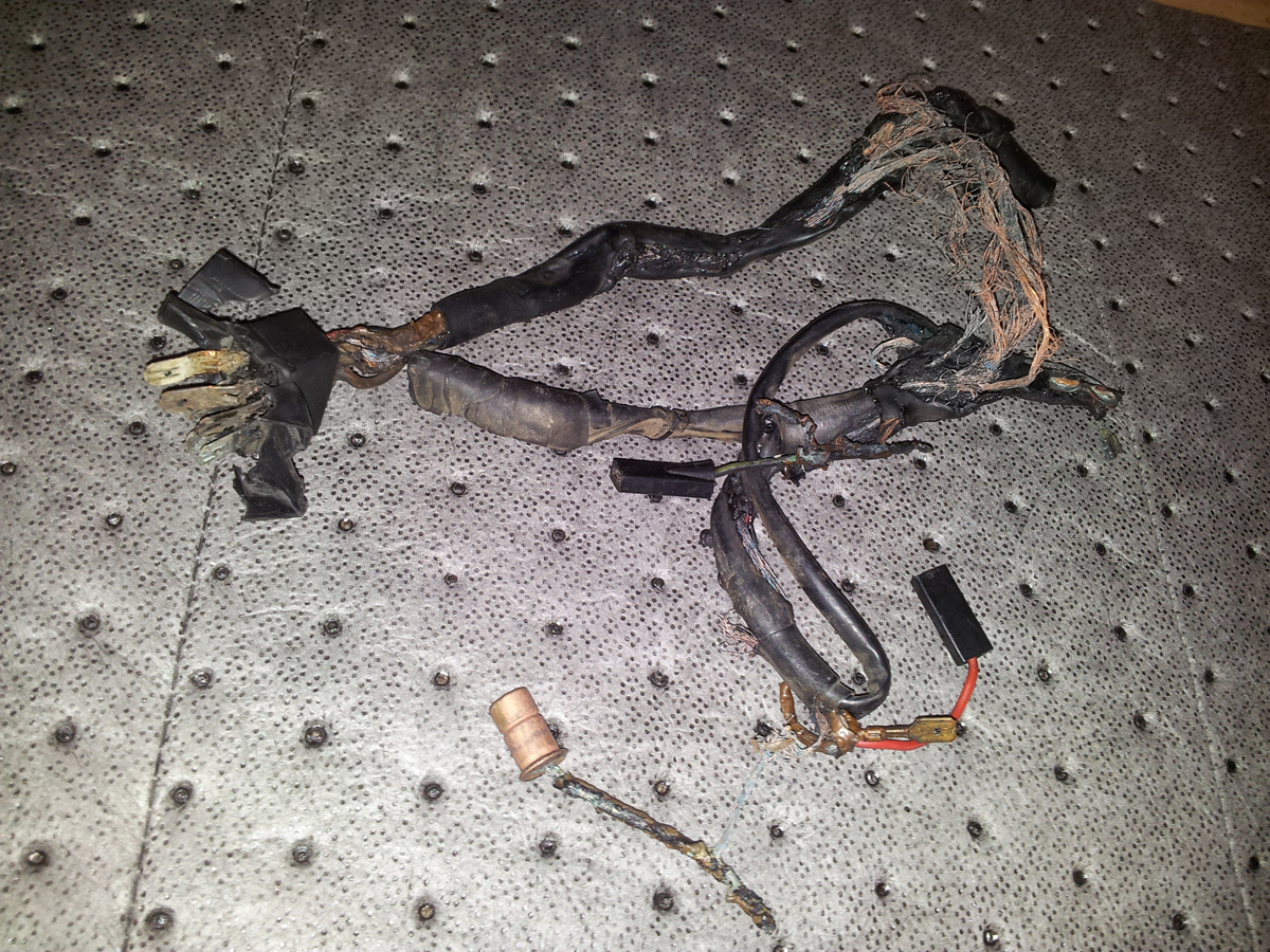
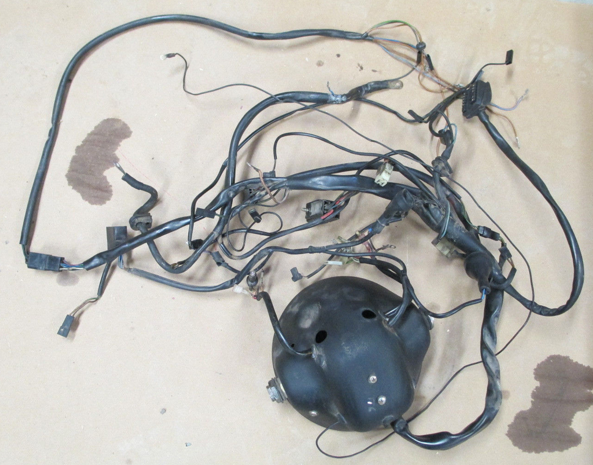
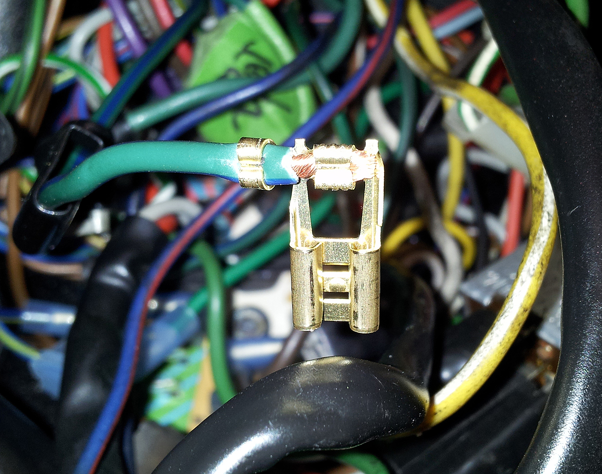
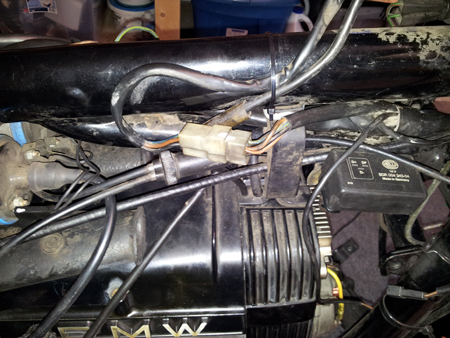
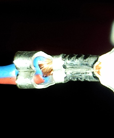
And the damage went all the way back through the harness. Some of it
looked fine, but beneath the plastic sheathing, there was carnage. Here's a
section from the headlight bucket down to a connector that joins to the
turn signals. It got so hot that the connector melted together and had
to be pried apart.
None of this was typical. Most airheads do not barbecue their wiring
on a whim. While I was not able to determine the exact cause of the
conflagration, I have two theories. One is that there was a short
somewhere in the old wiring. I certainly found a fair share of poorly
done bodges in the old harness. A more plausible explanation came from
Rick at Motorrad Elektrik, who
is the go-to guy for anything having to do with boxer wiring. He said
such extensive damage was rare, but he had seen some that overheated
when the headlight relay shorted.
Turns out that on an airhead, the headlight is not fused. If the
relay shorts, the wiring harness gets full voltage and heats up quickly.
This makes the most sense. When it happened, I hit the kill switch and
turned the ignition key off, but the headlight remained on until I
disconnected the battery - indicating a direct short.
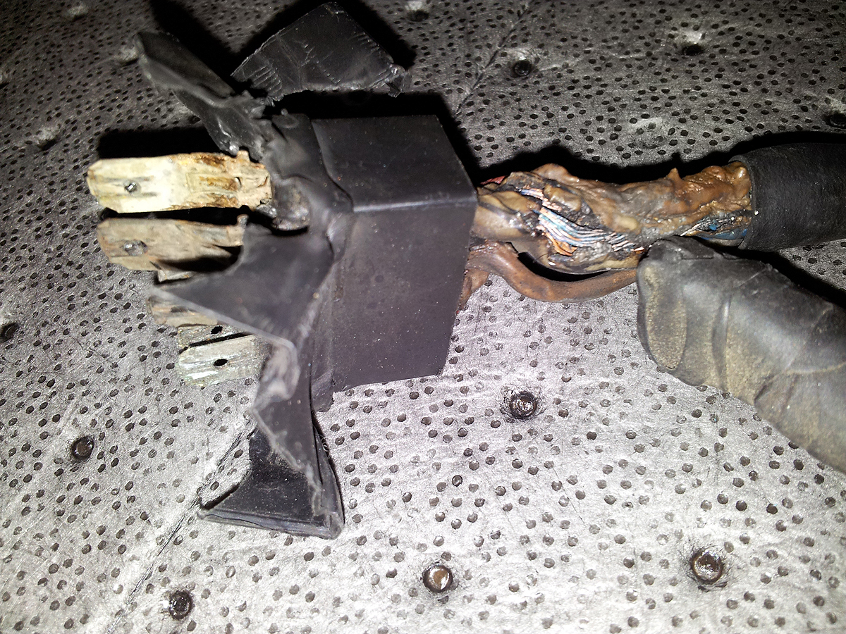
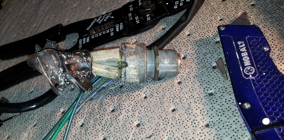
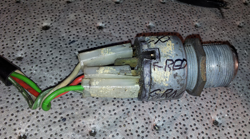
Then there's the relay itself.
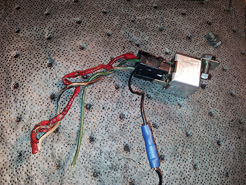
Yes, that's fried. And no, I did not put that barrel crimp connector
on.
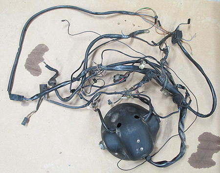
Regardless of the cause, the extensive damage meant the whole wiring harness would have to be
replaced - a daunting and expensive proposition. New, complete wiring
harnesses are listed for around $700. They are also listed as "no longer
available." Really handy people with lots of time on their hands can
create their own harness, either duplicating the original or going full
custom. I went the third route and hit E-bay, finally settling on a used
harness, complete with headlight bucket and every bit of wiring,
including the connector for the instrument pod, from a one-year-older
model R100RT in good shape for a little over $100. Because the seller had not
ripped the wiring out of the bucket, that meant I'd save some time and
effort, since I wouldn't have to thread as much wiring into the bucket.
It was important to get the right harness - wiring changed somewhat
every few years, and the RT/RS harness includes wiring for the clock and
voltmeter. I purchased the closest thing I could get to the original
harness for my year and model.
Replacing the whole harness was actually for the best, as it gave me
the opportunity to correct a lot of issues.
The Saint's bike |
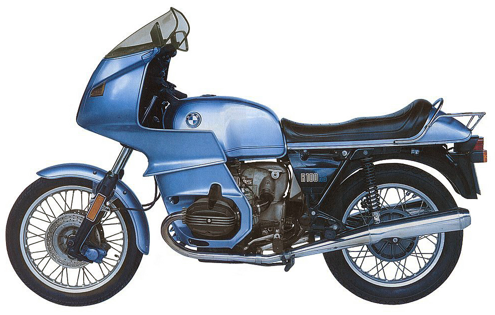
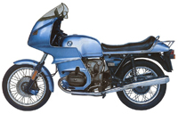
You see, my old airhead had a hard life. It came into this world as an R100RS
with a big touring fairing, like the one Roger Moore rode in the TV show
"The Saint. It went through several owners, including one who tried to
convert it to a "CS" model, which was BMW's '80s update of the venerable
R90S, with the classic bullet-style bikini fairing.
That meant a bunch
of wiring and hardware changes, since the RS has a full dashboard where the key resides, and
front turn signals up in the fixed fairing instead of on stalks. Eventually it wound up
in the hands of a well-meaning BMW car enthusiast (yes, BMW makes cars
too!) who "restored" it. I've been dealing with the fallout from those
previous owners ever since.
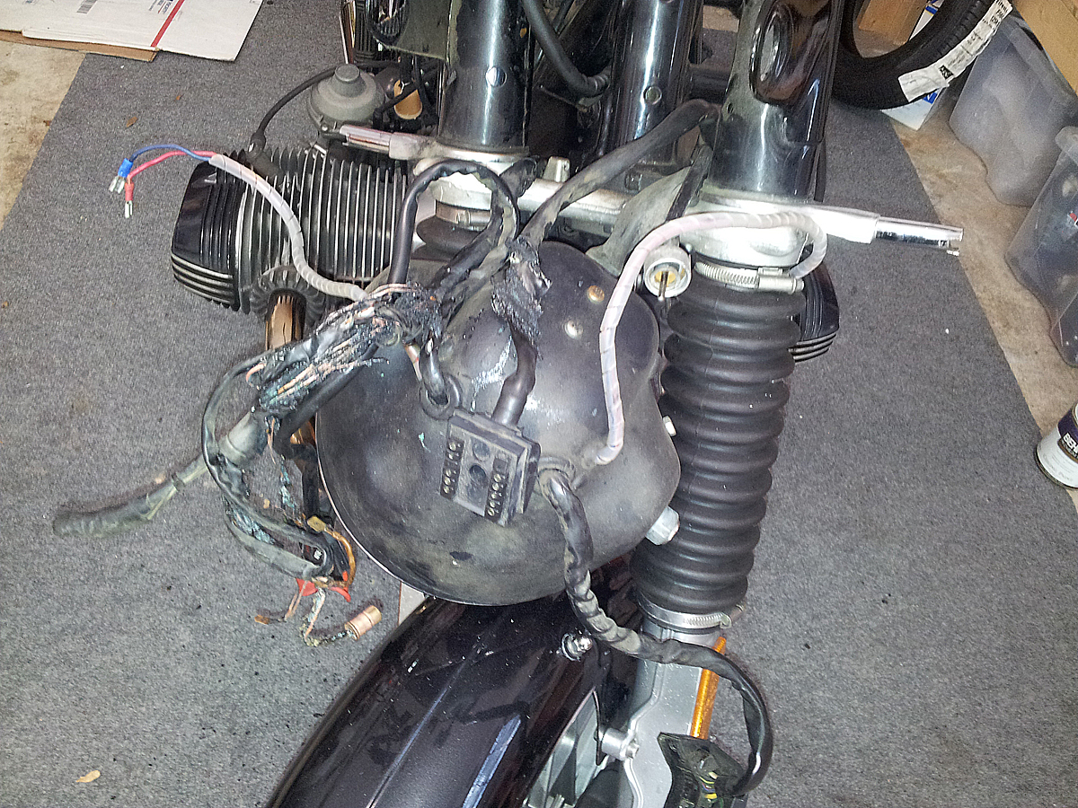
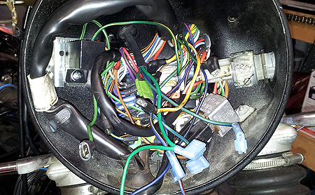
For instance, living inside the headlight bucket there were some
seriously WTF things
like this...
and this...
Wire nuts? Really? And I don't care how much military-grade rubber
tape you wrap things up in - you are doing it wrong. Very, very wrong.
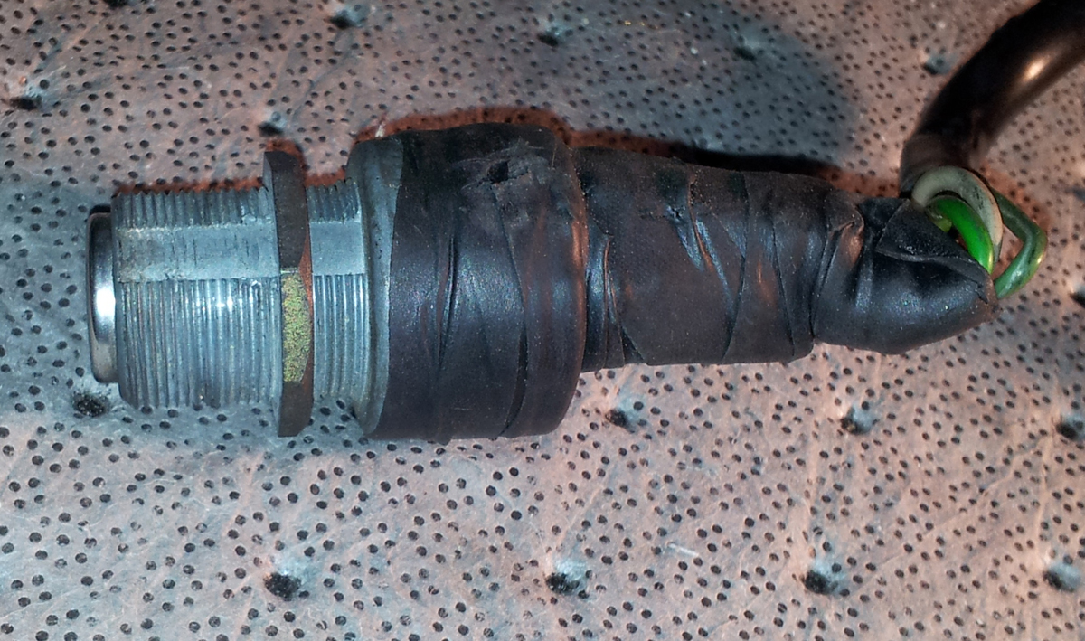
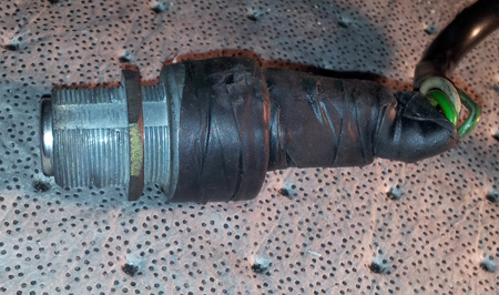
That ignition barrel? Careful, archaeological-quality unlayering
revealed this:

It's a wonder the bike ever started with that. It's a wonder nothing
caught on fire sooner.
Before total disassembly, I made sure to mark everything.
In fact, before taking off the old harness, I took pictures of the
routing, because the replacement harness should follow the routing
exactly - there's not much room for error, and you want everything to
reach without rubbing or being pinched. I probably took 40 photos for reference - how wires were routed, how
and where they were secured, where the connectors were. It doesn't
matter how good the pictures are - as long as you can tell what is going
where, because you will NOT remember where it all goes. I also used tape
to tag parts of the old harness and indicate what went where for
comparison when I put on the new one.
Since I had bought the harness with the bucket, I just had to set the
bucket in place and run the main trunks back onto the frame and connect
everything up, using the photos as reference. That part was fairly
straightforward.
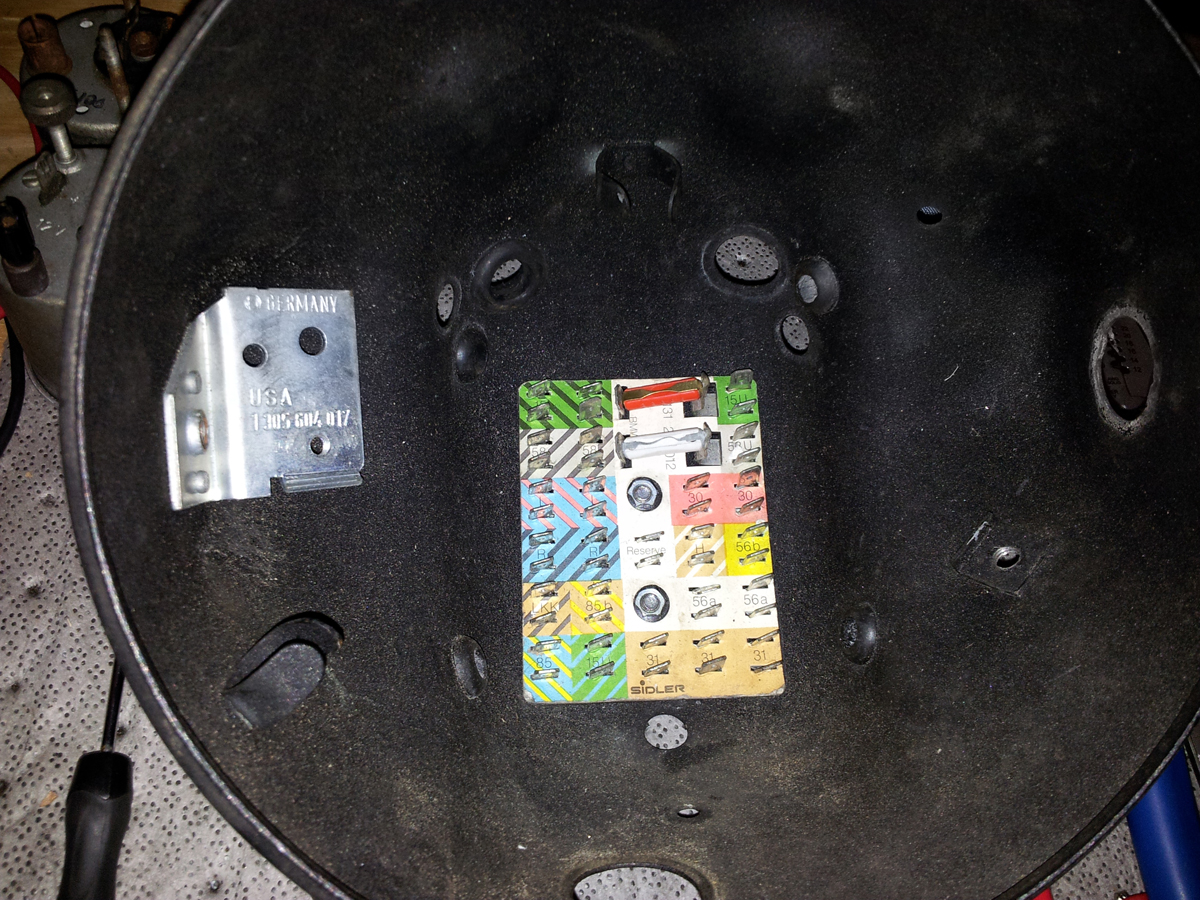
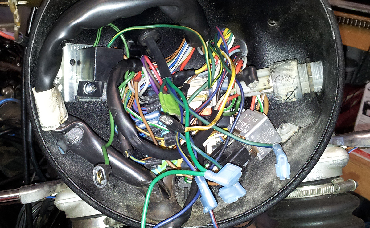
The real fun was up inside the headlight bucket, which is the heart
and soul of the system. On old airheads, everything connects up to a
festively-coloured board in the back. That's an empty bucket and board on the right.
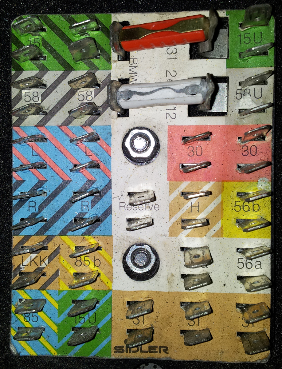
In theory, wiring everything up is ridiculously simple. The board has
spade tabs set into coloured areas.
 The
colours correspond with the colours of the wires in the harness. All you
have to do is match the colour of the wire to the colour on the board.
So if you have a green wire, it plugs onto one of the tabs in the green
area. A red wire plugs into the red area. If you have a green wire with
a black stripe, it goes on a tab in the green/black area and so forth. It's an
incredibly clever system - simple, logical, German. The
colours correspond with the colours of the wires in the harness. All you
have to do is match the colour of the wire to the colour on the board.
So if you have a green wire, it plugs onto one of the tabs in the green
area. A red wire plugs into the red area. If you have a green wire with
a black stripe, it goes on a tab in the green/black area and so forth. It's an
incredibly clever system - simple, logical, German.
Unfortunately, we are not dealing with a brand-new entirely stock
motorbike with factory-correct and matching model-year parts. In
the course of 30 years it had been hacked, bodged, repaired and rigged.
The same goes for the used part that was being retrofit.
Wires of a certain colour on the new (used) harness did not always
match wires from the old harness, when I could tell what colour the
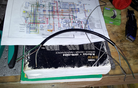
wires were before they were cooked. Also, I employed three different
diagrams. The ones in my two old manuals are black-and-white, with wire
colours indicated with letters, but the letters were not intuitive. For
instance, black wires were indicated with "sw," which is short for the
German word for black, "schwartz," and other abbreviations were for the
German too. Additionally, none of the wiring diagrams entirely agreed
with one another, or with what was on the harness. The most useful diagram was this one, in colour.
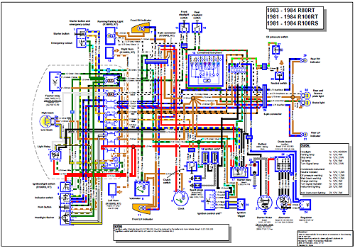
However, it is for a European spec RS/RT, so the turn signals are in
a different place and it includes an on/off switch for the headlight on
the left switch assembly.
It can all be overwhelming. The best advice is to take things slowly,
one wire at a time, and stop when you get frustrated. Things will be
much clearer when you come back to it another day. Beer helps.
The biggest issues I ran into involved the switchgear, which was not
included with the replacement harness, and turn signals; the harness
was from an RT, with signals in the fairing.
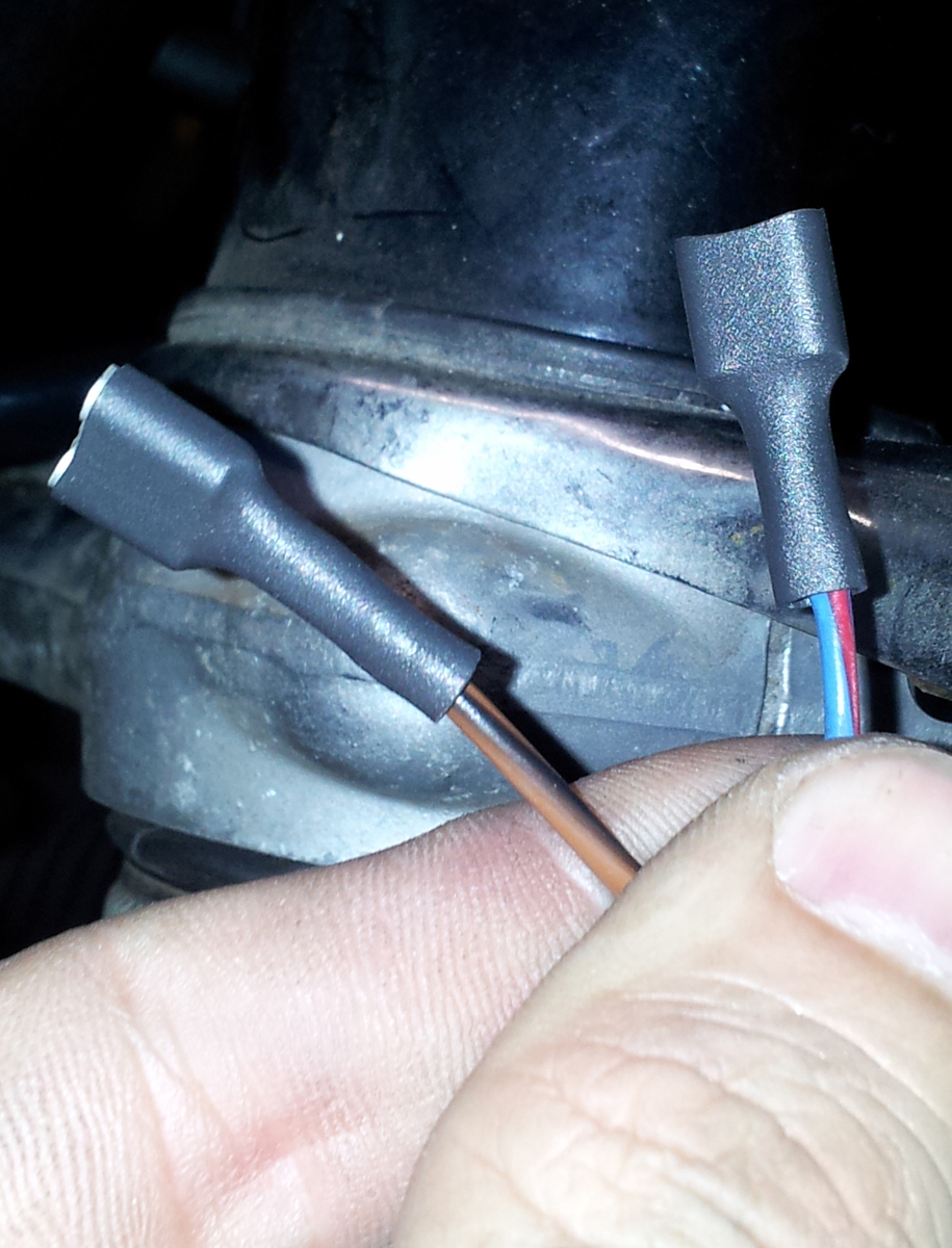
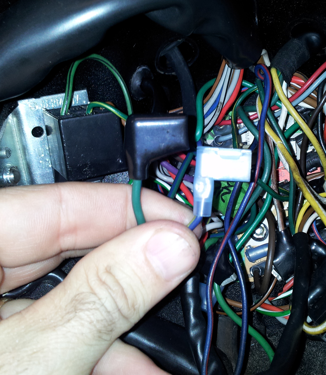
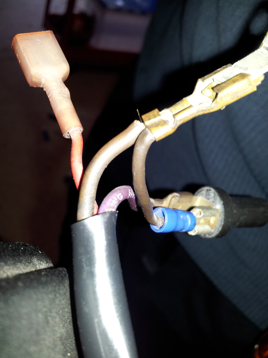
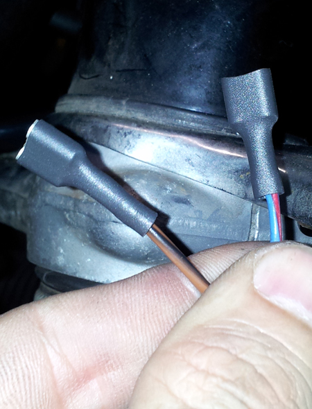
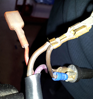
Signals first... Here's a close-up of wiring that was on the bike:
On an original BMW, the hot wire to the right turn signal is blue
with a black stripe and the ground wire is brown. The left signal is
blue with a red stripe and another brown. This is none of those. It also
has exposed female spade connectors from Lowe's and cheezy plastic wire
protector stuff from an auto parts store. That's fine if you're in a
bind and need a temporary fix. But it is not right.
My initial inclination was to do a functional-if-incorrect fix of my
own, but after some deliberation (and beer) I decided that since I did
not need the bike to function immediately, I would do it properly, even
if it meant taking a longer time - the "waitin' on parts, man!" portion
of any project.
I salvaged the proper colored wires from an uncooked section of the
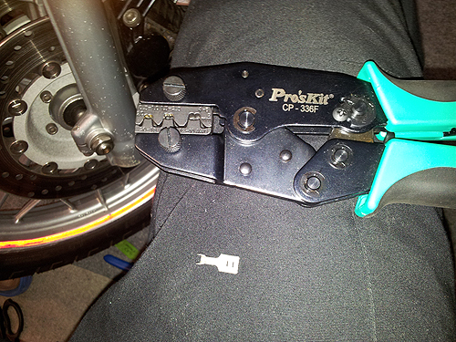
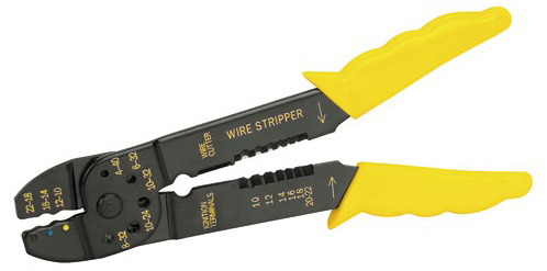
old harness. I also ordered factory-style, crimp-on connectors and a
crimping tool from
Cycleterminal.com. Service was fast and I'll deal with them again. Good folks.
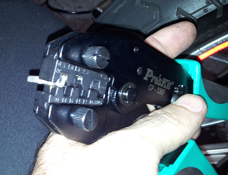
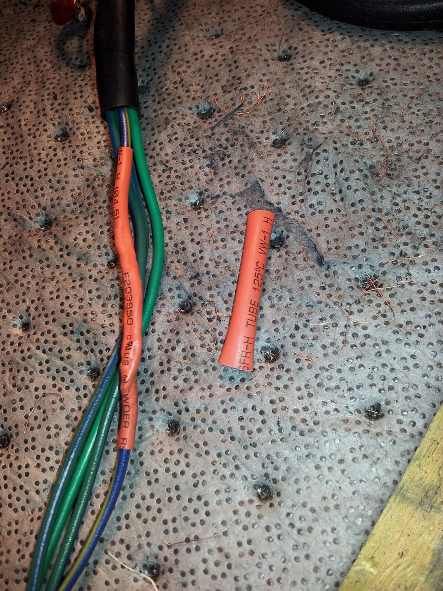
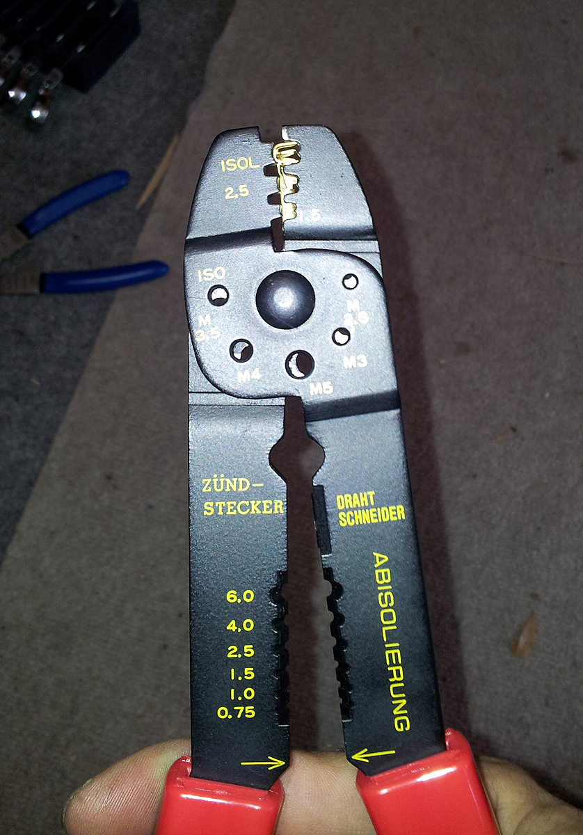
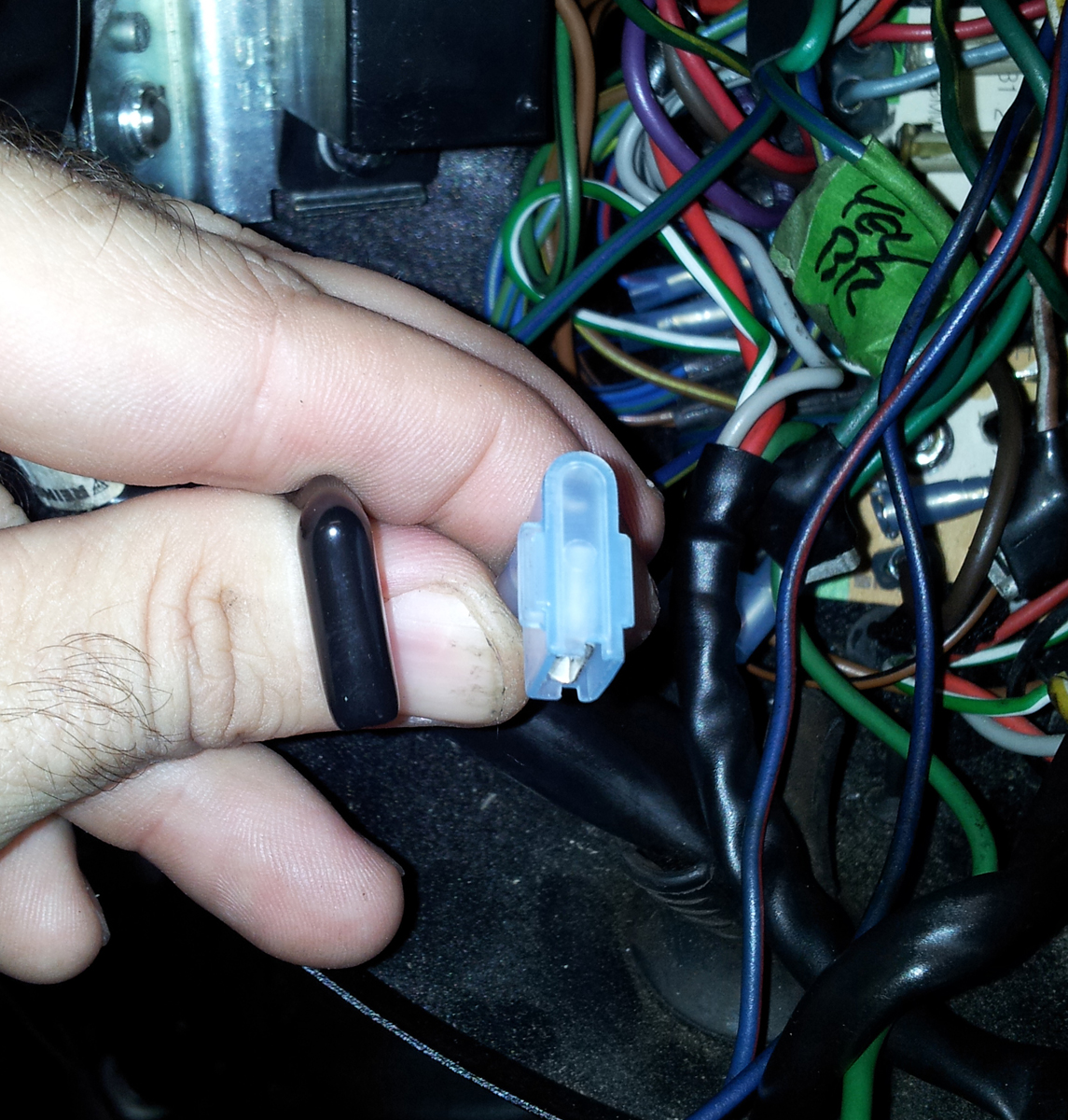
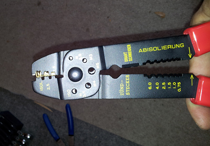
Here's the tool and a connector.
Basically, you just strip off a small bit of insulation from the wire
(no more than 3/8") and twist the strands. Put the connector in the die,
slide the wire in and squeeze.
The die has two sections - one crimps around the wire at the insulation
to provide strain relief and
the other tightens the bare wire securely to the connector, at the same time.
It takes a little practice, and the tool costs more, but the results
are far better than anything you'll get with the typical hardware-store
connectors and crimpers. Once the connectors are on, cut some heat
shrink tubing and hit it with the heat gun.
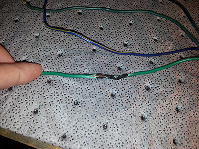
OCD readers will note that in the picture above, I used a brown/black
wire rather than plain brown for my ground. Unfortunately, I couldn't
salvage enough plain brown wire. Some future mechanic will probably
curse my impropriety.
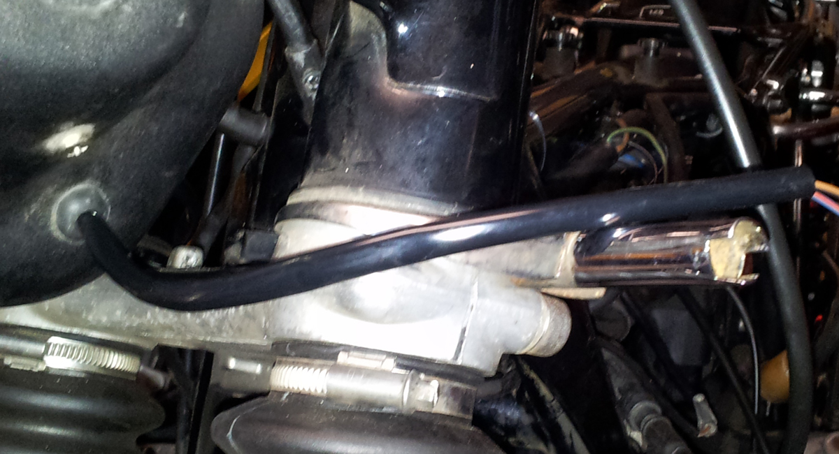
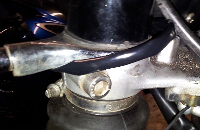
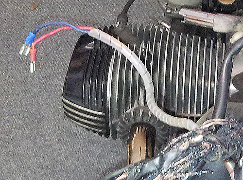
On a proper R100/7, the wires for the signals run from the headlight
bucket through small holes in the fork covers and out to the stalks.
This would require removing the forks and while I want to do things
right, that's hours of additional work. Instead, I ran them behind the forks, to the
stalks, wrapped in factory-style black sheathing. Everything is
therefore weatherproof and since the stalks move as a unit with the
forks and headlight, there is no chafing. When I service the forks, I'll
route the wires properly.
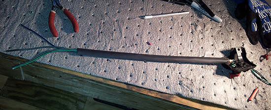
The switchgear was in reasonably good shape, but the wiring had been
damaged by contact with hot wires. Mostly it was just melted insulation.
I cut away the protective sheathing to assess the damage.
Fortunately, most of it was at the far end, away from the switch. Since
the bike had been converted from "RS" to "S," it had shorter handlebars.
But the previous owner hadn't bought "S"-style switchgear, so the wires
were longer. That was a lucky break! It was then just a matter of cutting off the irreparable
wiring at the far end and repairing the remaining damaged insulation with some heavy-duty heat
shrink.

And then sliding the wires into a new sheath.
You'll note that there are no terminals on the end of the wires up
there. That made the wires easier to thread into the headlight bucket.
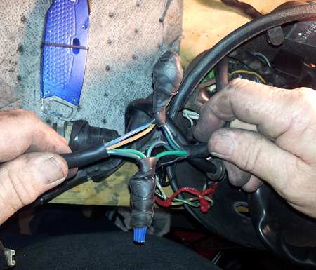
Once inside, though, things got tricky.
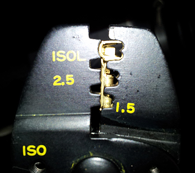
Because the designers put a headlight in the headlight bucket, in
addition to wiring, they needed plenty of room. You can't use a normal
connector like this:
Plugged straight into the board would mean you lose almost an inch of
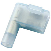
depth to make room for all of the wires, robbing valuable space. Instead, the
factory uses a right-angle
gizmo called a "flag terminal," I guess on accounta it looks like a flag
when the wire's attached. This puts the wires out to the side.
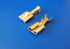
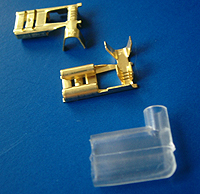
The ones available at your local auto parts store look like this:
That's what I bought, initially. And I started installing them.
However, in addition to not being factory-correct, I quickly
found another problem. They were too large! The tabs on the board are
fairly close together and everything's a tight fit. I was not going to
get all of the connectors on.
The proper solution
would be to get factory-style flag terminals, again from Cycleterminal.
I also ordered black insulators rather than the clear that you see in
the picture.
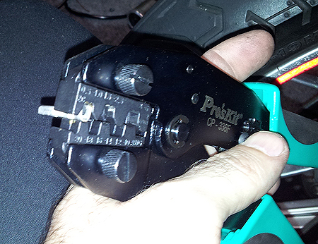
However, because of their design, the regular die on the crimping
tool does not work on the flags. To make a long story short, I ended up
using a German crimping tool from
Goodspeed Motoring.
Sure, it looks like the generic stripper-crimper you can get at Harbor
Freight.
But get closer. The jaws of are made to hold the connector at the base
and fold the tangs over.
And that makes all the difference. With a little practice, the results
are factory-grade.

Note that you have to put the insulator on BEFORE attaching the
terminal. Duh.
Here's the difference between the factory-style and auto-parts
generic terminals once installed. There's not much difference in length, but the
factory style are much thinner - and most importantly, fit on the board.
The final task would be to sort out the wiring for the clock and
voltmeter. The eBay harness came with the wires in place, but they too
had a serious case of WTF. Here's the wires to the volt meter. Look
closely, because there's a lot of WTF going on.
The only thing right about this? Somebody used brown wire for
the ground. What's wrong?
- That purple wire does not exist in the BMW universe. It
should be grey with a black stripe.
- The red wire should be green with a black stripe.
- The red plastic insulated terminal is crap.
- The purple wire is hot - note that it ends in a
non-insulated crimp-on connector.
- There's a cheap blue insulated crimp-on for one negative
terminal.
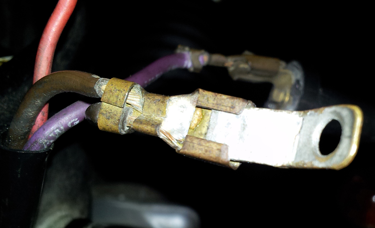
The other negative terminal? That is a work in itself.
|
 |
 |
That's an industrial-grade connector, but the wrong
type. It should be a male spade. Obviously, someone didn't
have one of those lying around, so they cut off a random bit
of scrap metal, stuck it into a female connector, and
voila! Instant spade terminal! Brilliant! I can see
doing something like this as a temporary fix on the side of
the road. Electrons will flow through it. But as a permanent
solution? What kinda crack were you smoking that day? |
The only solution would be to start from scratch, again using the
proper coloured wires.
Not difficult, but you wonder why the previous owner didn't do this
in the first place.
With everything repaired, I checked and triple-checked all of the
connections to make sure the proper wires were plugged onto the proper
terminals and that nothing was left hanging, and therein lies an
important point:
Since this was my first major wiring overhaul, I probably spent as
much time staring at things as I did doing actual work. I stared
at wires. I stared at wiring diagrams. I compared wires to wiring
diagrams and stared some more. When my eyes glazed over, I took a break
until I was clear-headed enough to return to staring. Because the
potential consequences of getting it wrong were so great - FIRE! - I
really did not want to screw anything up and there was a lot of anxiety.
In the end, though, it was not a difficult project. The basic concept
- match the colors! - is stuff learned in kindergarten. The devil is in
the details: having patience, taking your time, using the right tools
and the right parts.
With everything plugged in, it was time for a test run. Conscious of
the possibility of fire, I rolled the bike outside and connected the
battery. Nothing happened. That was a good sign.
Next, I turned the key.

The headlight came on! I had high and low beam. I had left and right
turn signals, brake lights and idiot lights on the gauge cluster. I felt
the wires inside the headlight and on the harness; nothing was heating
up, so I put on the fuel tank. After sitting a few weeks, it took a few
tries, but the bike finally started and ran like a champ.
In fact, a few things are better than before. The turn signal
indicator on the gauge cluster now works, as does the neutral light,
which was hit-or-miss. There was also some cross-talk in the turn
signals before - a left turn signal would also cause the right bulbs to
glow dimly. Putting a meter on the battery revealed that it is charging
at 14.3 volts at 5,000 RPM, very healthy for an airhead. I also know
that all of the connections are correct - there are no half-assed fixes,
festively coloured wires or mystery lumps hidden inside layers of tape.
The whole project took about 16 hours of actual working time,
including staring. Some of that also involved redoing things, like
replacing the auto-store connectors I initially fitted. I probably spent
$250 on parts and another $75 on tools, all of which is a lot less than
a new harness (which you can't buy), never mind shop time - if there was
even a shop that would do the job within 100 miles, which there isn't. The experience and
knowledge gained? Priceless.

Return home |