One Thing Leads To Another
Life Lessons Learned Rebuilding Bing
Carburettors
Studies have shown that people tend to form an
unbreakable bond with the popular music of their teens and 20s, thinking
that most of what came before is quaint and what came after is crap.
Qualitative distinctions aside, as a product of the '80s, I have a
brain-stew of new wave, synth pop, hair metal, punk, early goth and
college radio tunes swirling around in my memory banks, and as I was
working on this project, the Fixx's hit "One Thing Leads to Another"
kept playing in my head. The Fixx were Brit new wavers who had a
couple of other hits ("Red Skies," "Stand or Fall," "Saved by Zero") and
are, according to the interwebs, still touring. "One Thing Leads to
Another" came out in late 1983, which makes it an age-appropriate theme
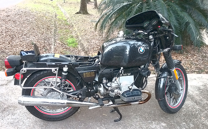
song for this project on my '84 R100RS.
The title is bang-on as well, since what began as
straightforward project turned into an extended trip down the Previous
Owner Rabbit Hole, with more than a few unexpected twists.
I've owned the bike for around 15 years, and as an
if-it-ain't-broke sort, I prefer to ride it rather than fettle (aside
from oil, filters, and routine maintenance). Over the years, it has been
relatively faithful, only bursting into flame once, but as the idle got
more erratic and simple tuning failed to cure the problems, I had to
face the inevitable: I was going to have to overhaul the carburettors.
I have plunged head-first into many things beyond my
skill set with little more than mild trepidation, but carbs scare me.
The last time I dismantled one was when I was 16, attempting to revive the
2-barrel on my first car, a '71 Plymouth Fury III wagon, using
little more than a couple of wrenches, screwdrivers and youthful
determination. When complete, I tried to start the car and a magnificent 6-foot
pillar of flame shot out of both barrels before the car finally ran,
poorly, and had to go to a proper mechanic to be sorted out.
While I'm now comfortable synching, balancing and
otherwise twiddling with settings, I had not yet attempted a full
rebuild,
sending the set from my ZRX carburettors off to a professional and fine-tuning
them later.
But I had been told that the Bings were about as
simple as carburettors get, and at its core, rebuilding is just taking
things apart, cleaning, and putting it back together with new rubbery
bits. How hard could it be? Unlike
valves,
there aren't even any maths involved.
 After
thorough research on the interwebs, I settled on a basic plan. The first
step was to ask Santa for an
instructional DVD from The Bing Agency. She delivered, and after
stewing over it for a year (because carbs scare me), I finally decided to tackle the job during the
following Thanksgiving and Christmas holidays so I could take my time
and not screw anything up. After
thorough research on the interwebs, I settled on a basic plan. The first
step was to ask Santa for an
instructional DVD from The Bing Agency. She delivered, and after
stewing over it for a year (because carbs scare me), I finally decided to tackle the job during the
following Thanksgiving and Christmas holidays so I could take my time
and not screw anything up.
A word about the DVD - even if Santa won't get it for
you, buy the damn thing. It's $30 (an hour of instruction for what you'd
pay for 20 minutes of shop labor). That's dirt cheap for serious
knowledge. Yeah, I know you can find YouTube how-tos for free because
I've seen those too, but this has them beat and no, I'm not getting
paid to say that.
However, while the DVD will show you how to do the
job, it will not help you deal with some of the inevitable pitfalls of
fettling something with three and a half decades of wear and abuse.
Ideally, this little how-to will fill some of those gaps.
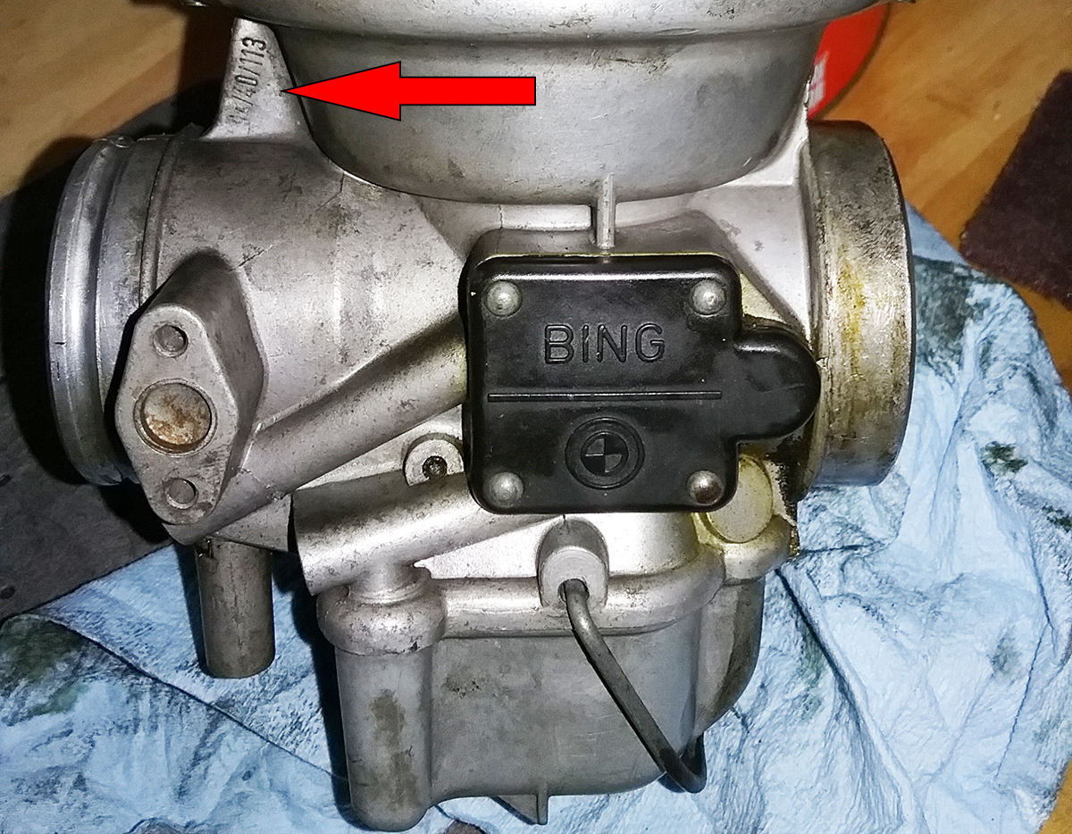
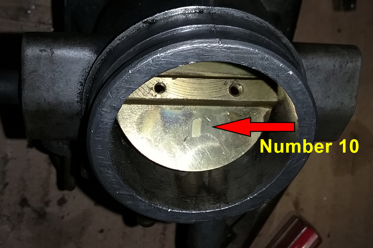
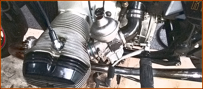
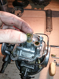
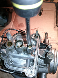
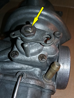
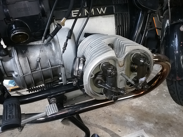
Before starting, I knew I'd need parts. To be sure you're getting
the right parts, make a note of the model numbers on the webbing of each carb in case you need specific things like jets or needles, or
want to know specific
settings, like how many turns of an adjustment screw. The numbers are on
the webbing at the top on the outside of each carb, just below the
flying-saucer-like diaphragm housing, as shown next to the red arrow
below.
 In
my case, the carbs are 94/40/113 on the left and 114 on the right. 94 is
the type, 40 is the size in mm and the last numbers
indicate specific model numbers for jetting, setting and parts purposes. The
Bing Agency has a chart of all of their carburetors with all of the
information you'll ever need. Click the image to the right and knock yourself out with
spreadsheet goodness. Print it out. Highlight the information for your carbs. You'll need it. In
my case, the carbs are 94/40/113 on the left and 114 on the right. 94 is
the type, 40 is the size in mm and the last numbers
indicate specific model numbers for jetting, setting and parts purposes. The
Bing Agency has a chart of all of their carburetors with all of the
information you'll ever need. Click the image to the right and knock yourself out with
spreadsheet goodness. Print it out. Highlight the information for your carbs. You'll need it.
|
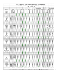
Click for carb reference chart |
When you're ready to spend actual money, rebuild kits are available from
various sources, including
The Bing Agency.
They range from $35 to $250 depending on what you need. Since I
hadn't taken the things apart, I didn't know exactly what I needed, but I
figured I'd go ahead and get something with diaphragms and floats just
in case.
I narrowed it down to two choices,
one from Bing and
one put together by Bob's BMW. The Bing kit had needles and needle
jets, but didn't include a lot of other replacement parts such as screws,
springs and rubber boots. Bob's didn't include the jets, but looking at
my carbs, I knew I'd need springs and boots, so I went with that. If I had it to
do over again, I would have gotten the Bob's kit and ordered
the needles and jets separately from Bing, but more on that later.
Next to those arrows, beneath the crud, springs. |
Step one: Preparation
Before doing anything, clean up your space and lay out your tools. At the very least, to start
you'll need:
• Phillips and flat screwdrivers
• Metric wrenches
• Picks for removing o-rings
• Small hammer and small punch
• Carb cleaner spray and a can of the solvent
of your choice.
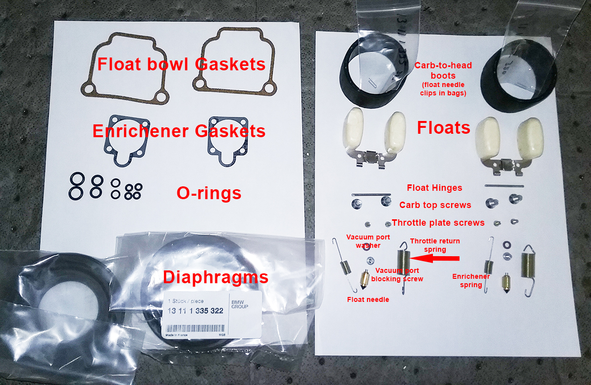
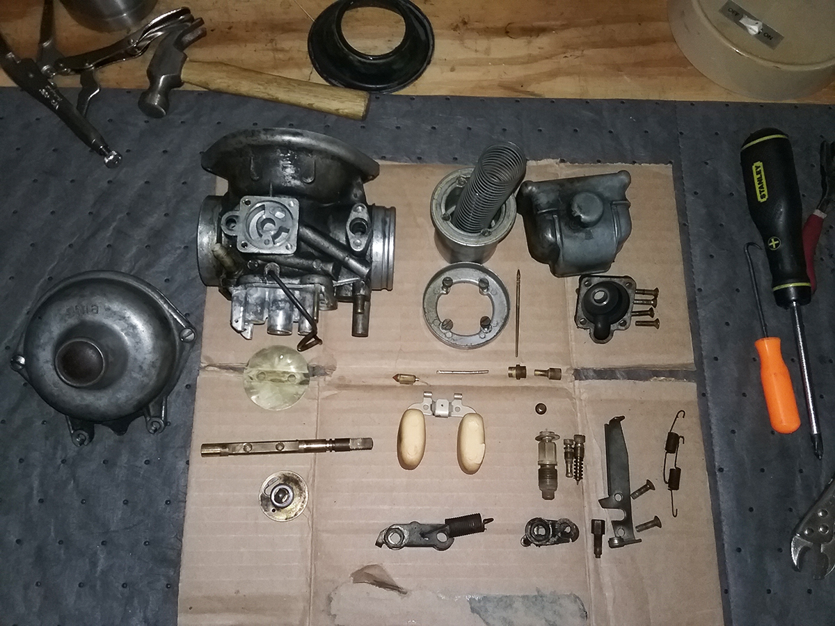
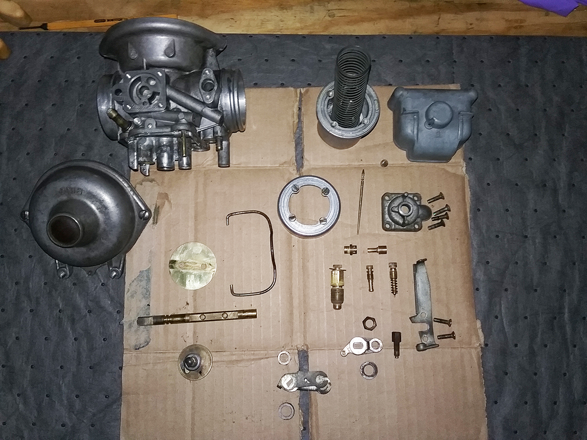
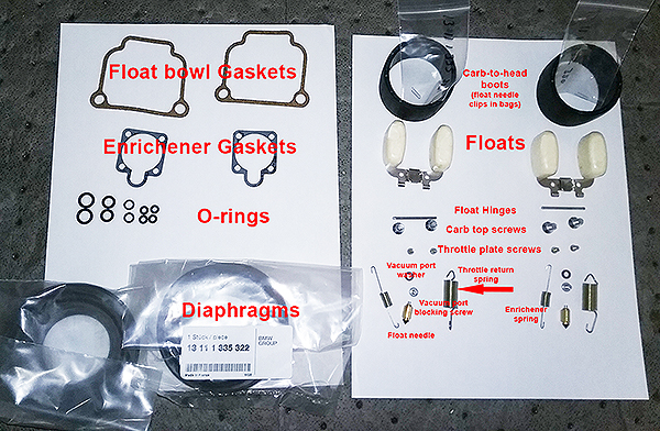
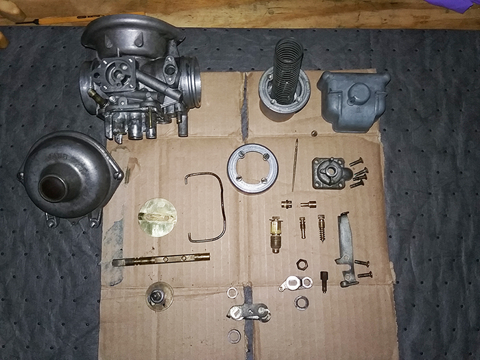
Once the parts arrive, take them out and organize
them. I did mine on sheets of white paper because I'm old and blind.
Here they are (you can click to see it larger):
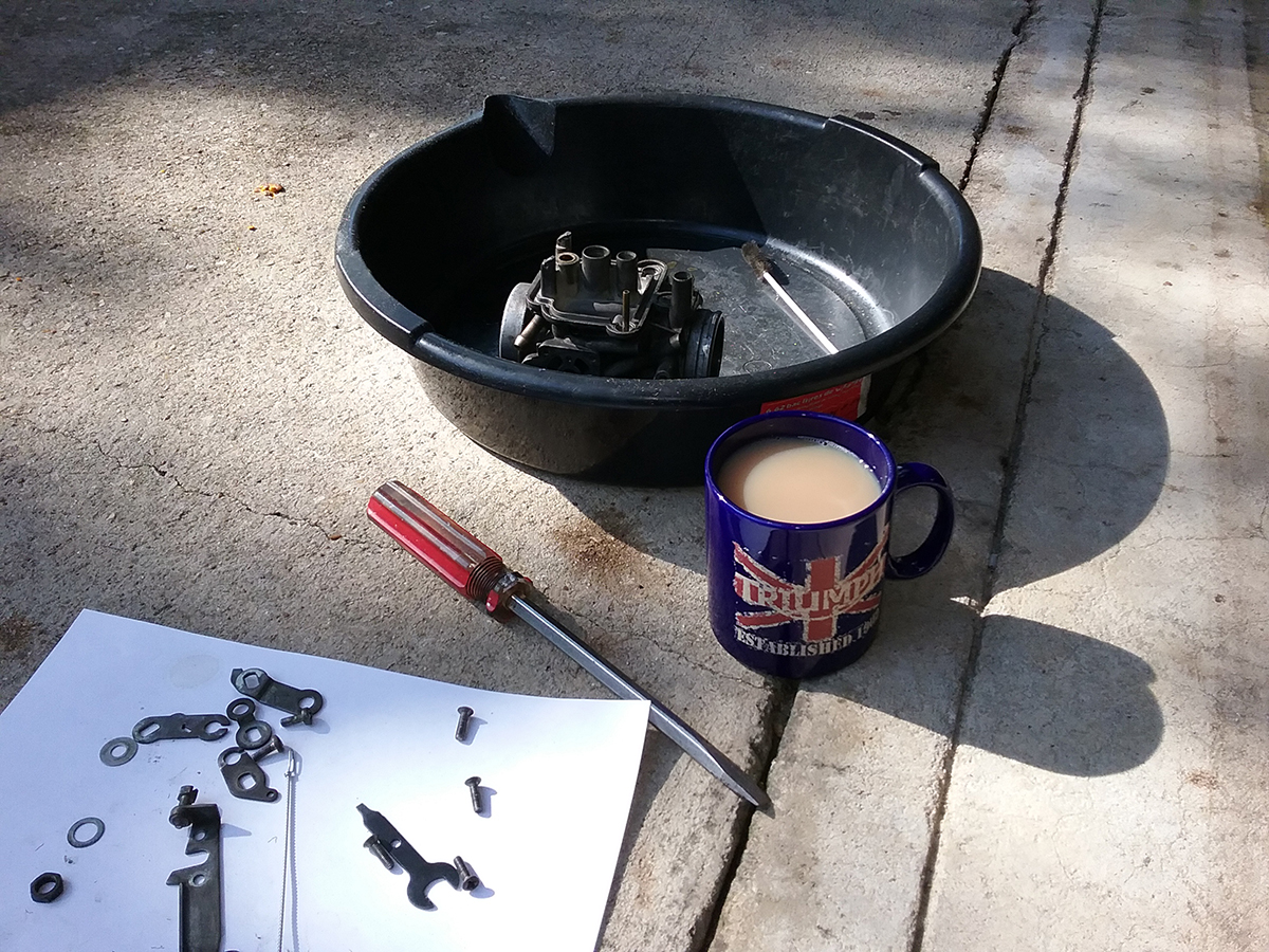
Step Two: Take everything apart!
Now it's time to get dirty and remove the carbs.
You can do this in any pretty much whatever order works best for you,
but DO IT OUTSIDE! Even with the float bowls removed, the carbs will
still have fuel lurking in the diabolical labyrinth of passageways
throughout the carb body:
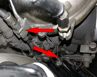
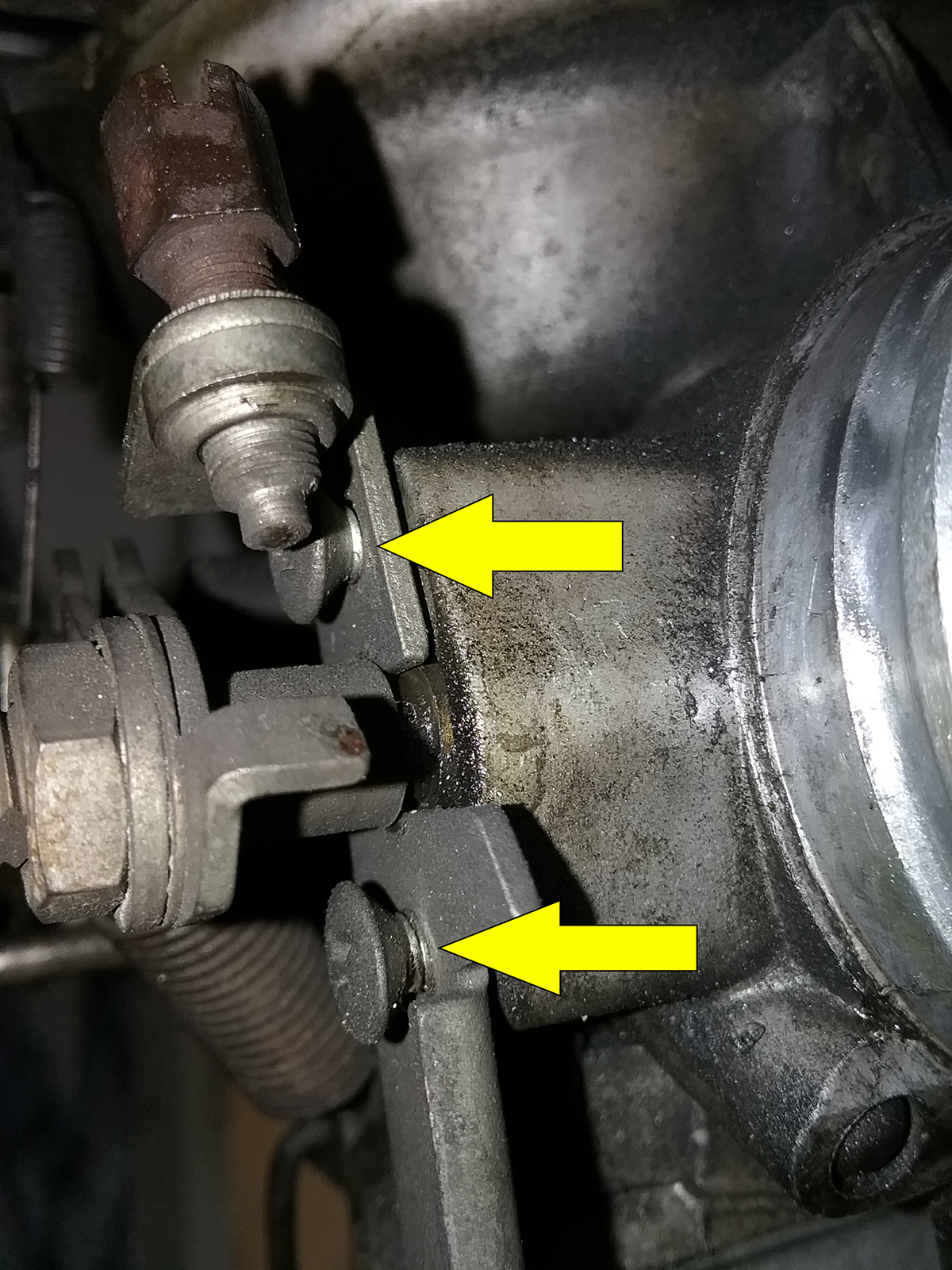
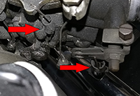
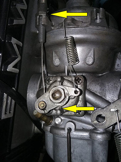
Remove cables by loosening the locknut (top arrow), turning the
adjusters clockwise all the way to loosen the cables, then move
the levers so you can slide the barrel end of the cable out
using the slots in the arms (bottom arrow, shown with cable
removed from throttle). Yeah, it's filthy. |
- Turn the petcocks off
- Disconnect the fuel line
- Slide the bail off the bottom, carefully remove the
float bowl and dump the fuel into an appropriate container
- Undo the hose clamps that hold the carb
between the airbox and cylinder head
- Remove the throttle and choke (yes, it's
technically an "enrichener," go away, OCD people) cables
- Remove the carburetor from the motorbike
- Drain all fuel into an appropriate container,
blow the passages out with compressed air and let the thing sit
outside so any remaining fuel will evaporate
You can remove one or both, but remember: rebuild each one separately
so you do not get parts mixed up. They are mirror images and some parts are
not interchangeable.
Once you have the carbs off, the real fun starts.
Fire up your laptop, portable DVD player or TV, if you have one in
your garage, and start watching the DVD. Really, get the DVD. Follow
along, doing exactly as instructed. Use the pause button between tasks.
Rewind if necessary. Watch twice, fettle once.
It's all there, and I won't bore you with every
detail since IT'S ALL RIGHT THERE! But I will give you the highlights
and cover some issues that are not covered in this tutorial.
Basically, disassembly is like Demolition Day on a
home improvement show - just tear it all down. But be wary: there are a
lot of tiny parts, screws, springs, nuts and bolts, any one of which
could sideline your project if lost. So go slowly, take pictures, label
things if necessary, and lay them out neatly in your workspace.
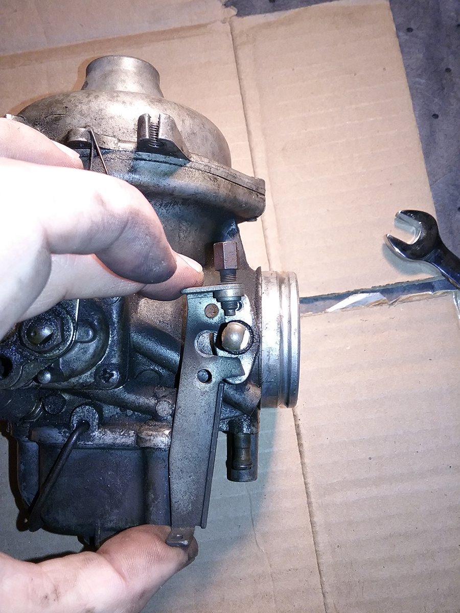
Here is what I started with.
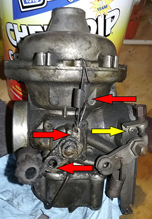
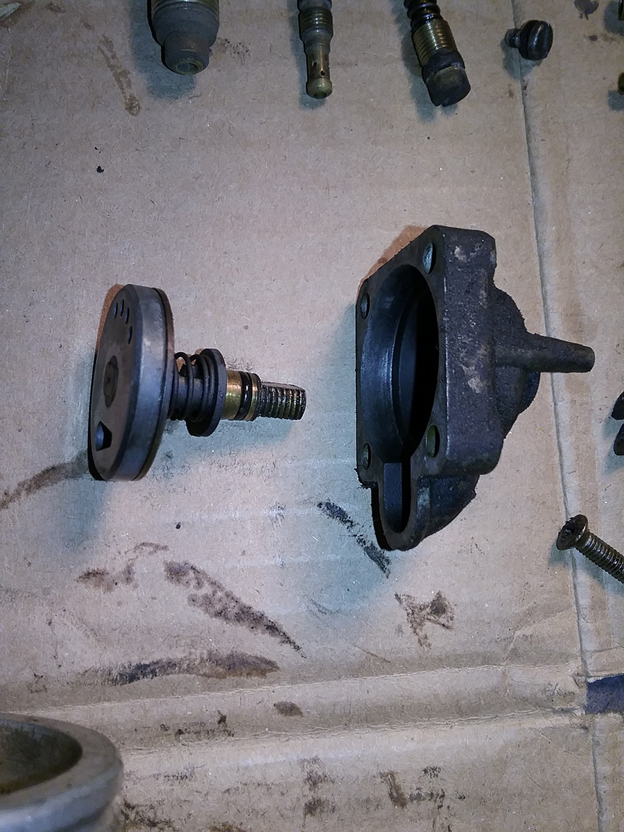
 Yeah,
that's nasty. Looks like the choke gasket has been leaky, as well as the
diaphragm at the top. That was sort of expected, right? It's old. What
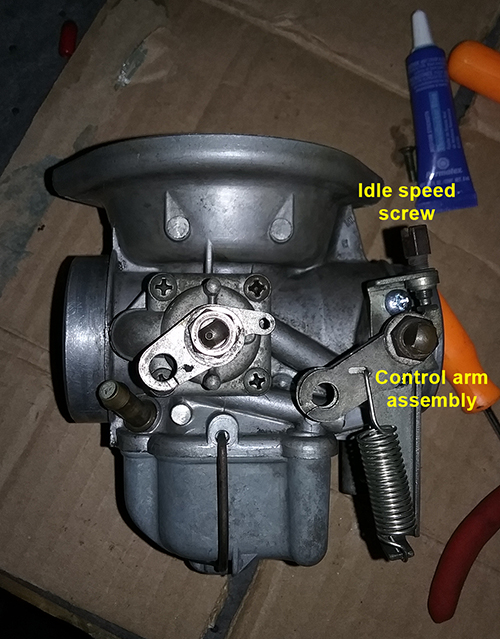
was not expected are the atrocities inflicted on the thing. Yes,
apparently someone has been here before, and they obviously did NOT
follow the instructions because right away we see, following the red
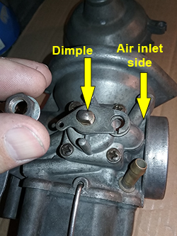
arrows from top to bottom: Yeah,
that's nasty. Looks like the choke gasket has been leaky, as well as the
diaphragm at the top. That was sort of expected, right? It's old. What
was not expected are the atrocities inflicted on the thing. Yes,
apparently someone has been here before, and they obviously did NOT
follow the instructions because right away we see, following the red
arrows from top to bottom:
• Two springs on the choke arm. Seriously? If the
choke wouldn't return, you put more springs on it? Like, instead of
finding out WHY it was not working?
• The choke arm (which is actually two pieces, one
with a slot and one without) is on upside down. The part with the hole
where the spring connects should be horizontal, not vertical.
• The arm piece with the slot to aid in removing
the cable should go on the outside, not the inside (see the throttle arm on the other side of the
bottom red arrow for the correct way). This is why it was damn near impossible to remove the
cable.
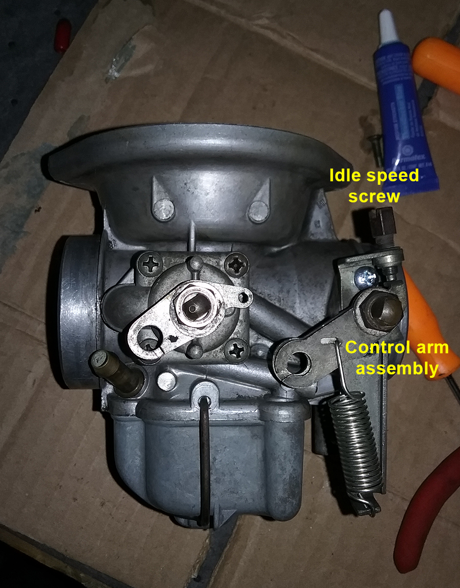
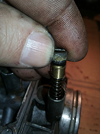
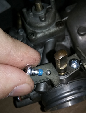
And then there are the yellow arrows, indicating the
wrong type of screw. That's a tapered screw head holding the throttle
actuator onto the carb. It should be flat. The tapered ends don't hold
the assembly, the screws are too long, and so the whole thing is loose.
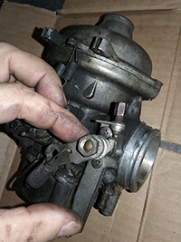
See the close-up on the right. I'm amazed the whole thing didn't come
off while I was riding it.
On to disassembly: After unhooking the springs, first remove the throttle arm (remember, it's
two pieces). Easy as 1-2-3
Throttle control assembly removal
|
1. Remove the nut to
remove the arm |

2. Remove two screws and the base |
3. Throttle actuator arm pieces. |
The choke lever comes off the
same way - one nut, two-piece arm. After that, remove the two screws
holding the top of the carb on. Sometimes they're phillips,
sometimes flat, but always be careful - they can be rusted or
corroded and therefore stuck. Try penetrating oil and/or heat if
they won't budge. Fortunately, mine were fine and the top came off
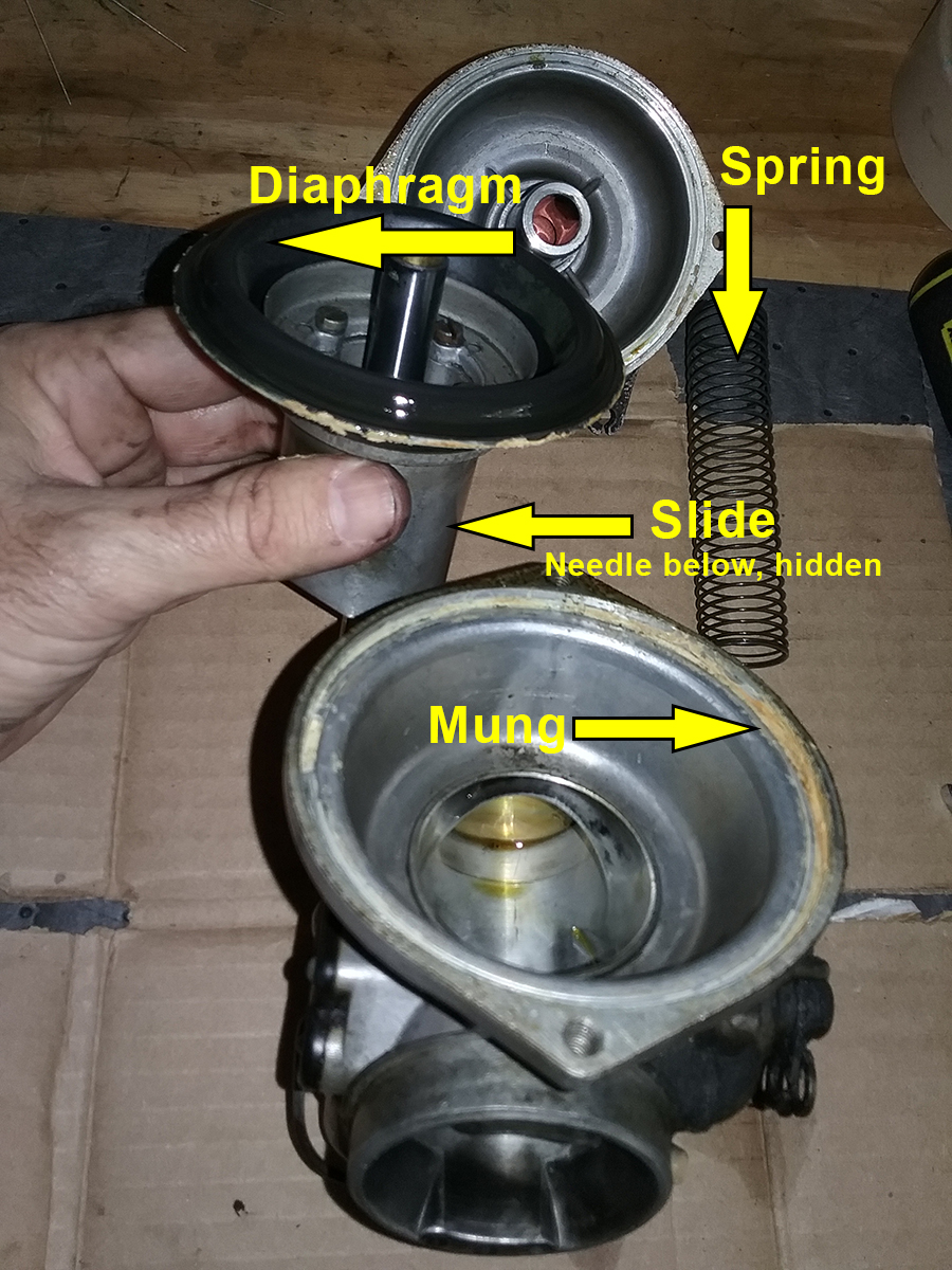
easily. Underneath, there's a large, floppy spring. Remove that,
then pull out the diaphragm and needle assembly, lifting it straight
up. Mine was not too bad, but it had years of mung built up. Yes, "mung"
is the correct technical term. Here it is coming apart.

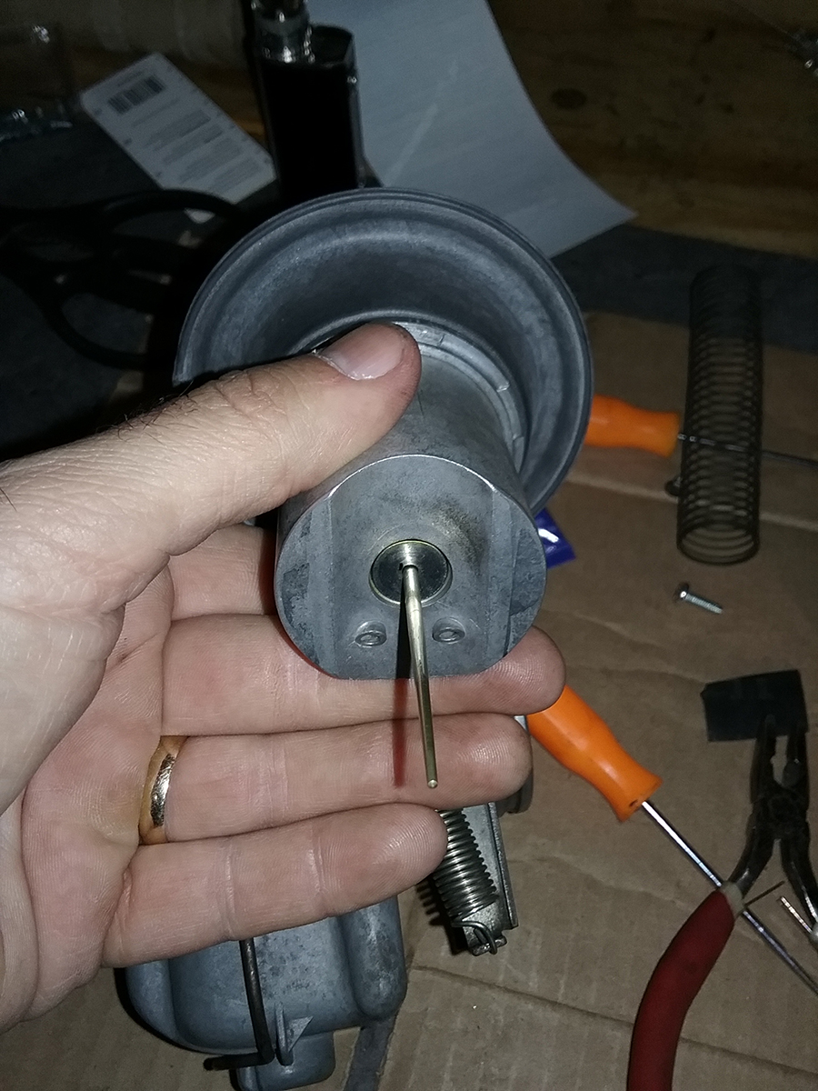
Four screws hold the diaphragm to
the slide. Remove those and remove the needle, which requires
twisting it a quarter turn at a time while pulling it - there are four slots,
or needle positions. Watch the video!
|
Diaphragm
retainer held by four screws
 |
Twist and pull
the needle to remove
 |
With the top of the carb apart
and carefully laid out, you can start dismantling the bottom. This
is where most of the magic happens, or witchcraft if you're so
inclined. So you have a cursory understanding of what's going on
with the parts the come off next, here are the very basics:
The bowl gets filled up with
fuel. Floats in the bowl rise with the fuel level, pushing on a
needle that stops the fuel flow when it's at the right level. Float
height determines how much fuel sits in the bowl - too much,
and it pisses all over your foot through the overflow tube. Too
little, and the engine doesn't get enough to function properly.
Floats are important!
With the fuel level correct, the
jets get to work. While "jets" sound cool, they're basically just
holes, but "holes" is not nearly as nifty-sounding. When the piston in the engine moves on intake, it creates a
vacuum. Air gets sucked in, but the negative pressure also means
that fuel gets sucked up from the bowl through the jets, mixing with
air and, if everything's correct, going into the combustion chamber
and exploding as the gods intended. "Rejetting," a favorite term of
hot rodding shamans, just means changing the size of the holes so
that the right amount of fuel is sucked into the engine with the
air. Too much, the mixture is rich. Too little, it's lean. It's
science! But it's also witchcraft, because different air densities
require different amounts of fuel to keep the ratio right, and if
you start messing with the exhaust, it gets really complicated. But we
don't have to worry about that (mostly) because these are "CV"
carburetors and everything is stock, but if you want to get deeply into the weeds
of fluid dynamics,
click here and enjoy the tech.
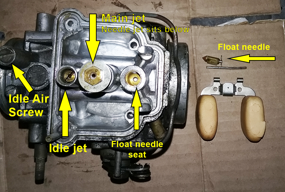
The Bings are pretty simple. There are
only three jets on this carb:
1. An idle jet, which is the hole
the fuel flows through at idle (duh!).
2. A main jet, which is the hole
most of the fuel flows when you turn the throttle.
3. A needle jet sitting on top of the
main jet. The needle jet is a tapered hole that has a tapered needle
stuck in it. As the engine speeds up, there's more vacuum, which
causes the diaphragm to pull the slide to which the needle is
attached, from the thick part of the needle to the thin, which
effectively varies the size of the hole (and the fuel flowing
through it) with engine speed.
There's also an "idle air screw"
which allows you to vary the amount of air coming through the carb
at idle (duh!), because the idle jet is a fixed-size hole, no
needle.
For the Bing, that's it! Simple,
right? Maybe not.
Now we take all that crap outta
the carb.
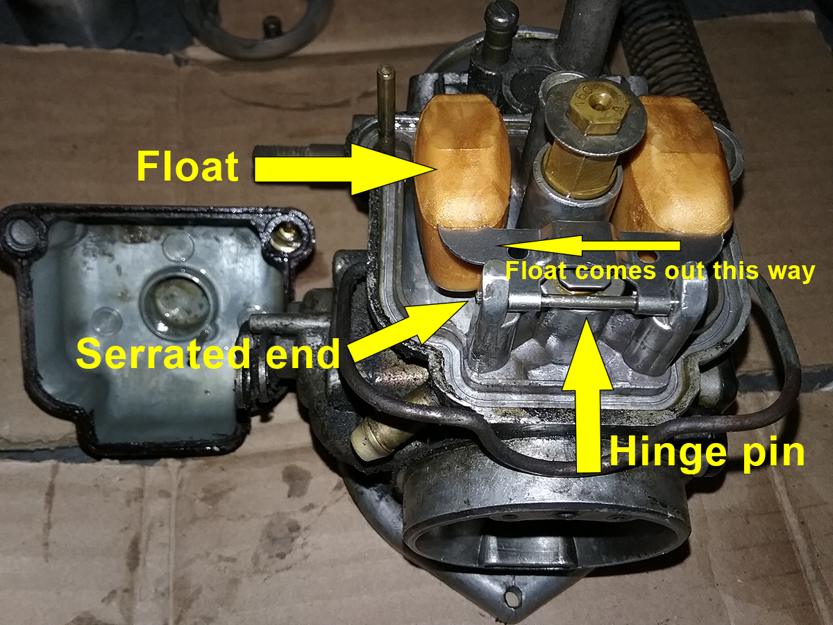
First, the floats. They're held
on with a hinge pin. One end of the pin is serrated. Take a punch
and a small hammer and gently knock the pin out from the
NON-SERRATED end and remove the floats and needle.

Here's the float out, and other
parts for reference before we yank them out. Yes, Hawkeye, that
hinge pin is bent. It happens. That's why the rebuild kit has new ones.

And out they come
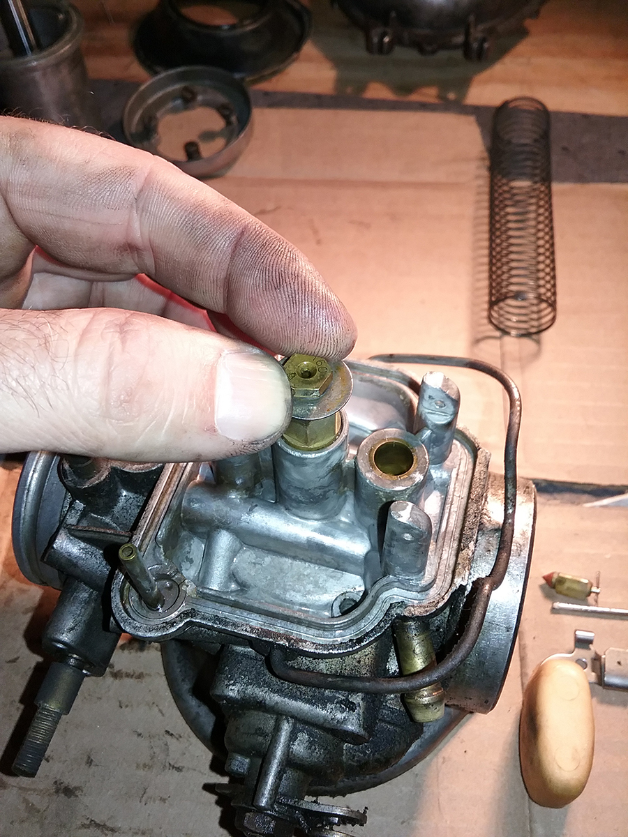
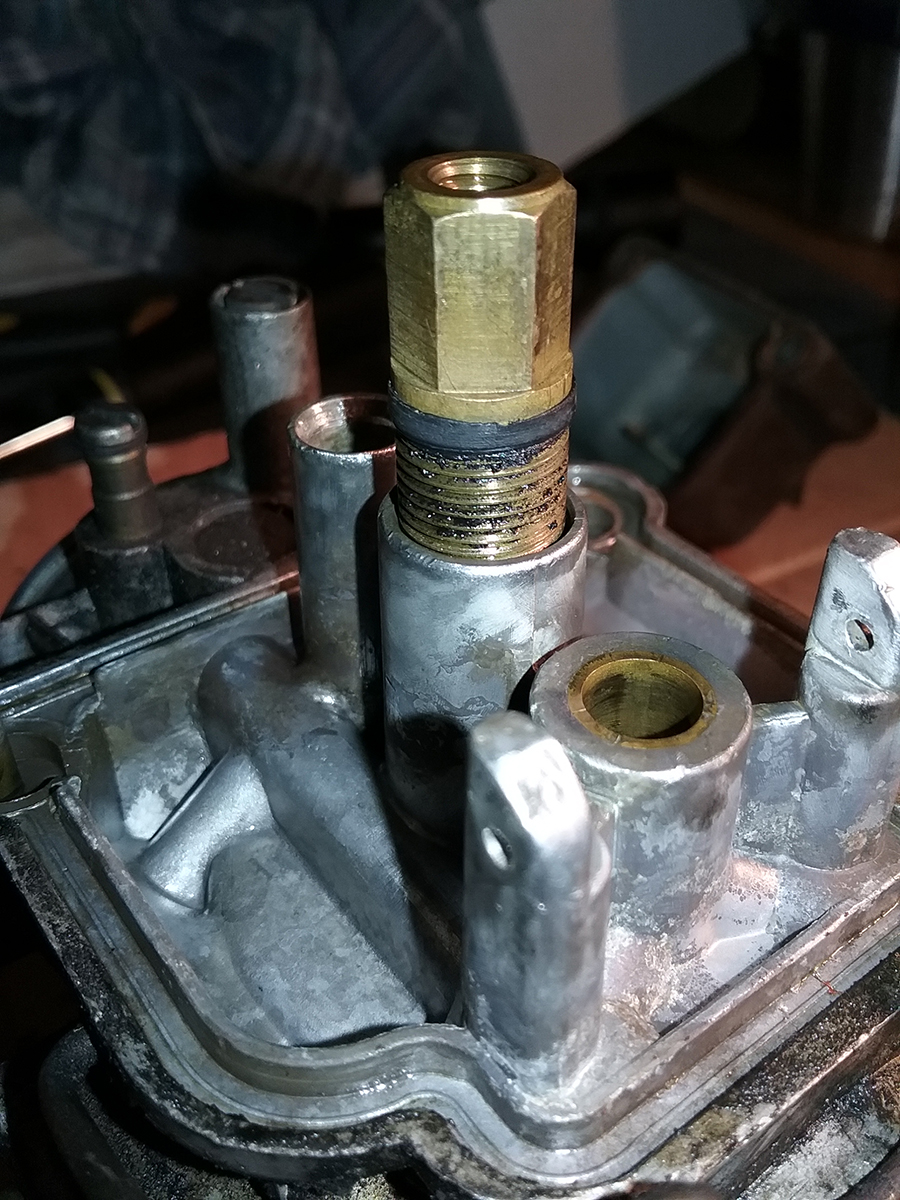
Main jet unscrews, with washer |

Main jet holder. Underneath is the needle jet, which may or
may not fall out. You might have to tap on that from the top.
Watch the video! |
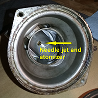
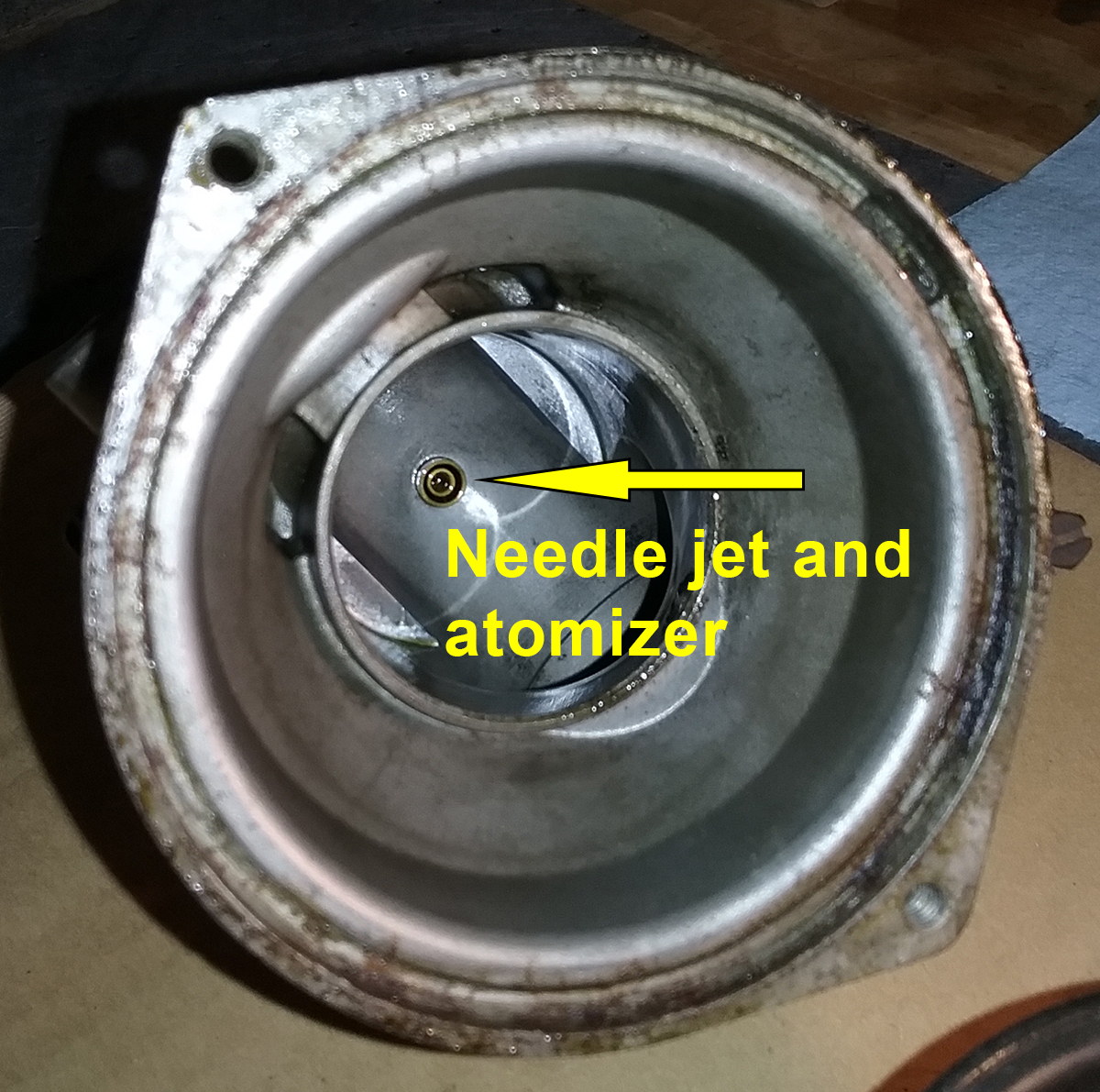
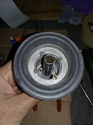
From the inside, the needle jet
and atomizer. A chopstick is really handy for tapping these
out if they're stuck. |
Idle Jet coming out |
Idle air screw and spring
removed |
Here's the idle jet removed from
its natural habitat. Note the condition of the o-ring.
Most were so brittle they broke apart when I tried to remove
them. |
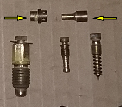
All jets and screws. The top
two are the atomizer and needle jet. Bottom, left to right:
Main jet, washer and jet holder, idle jet, and idle air
screw. Sorry the picture is crap, but you get the idea. |
Next to go is the choke assembly.
Four screws and it's off, then you pull the disc out.
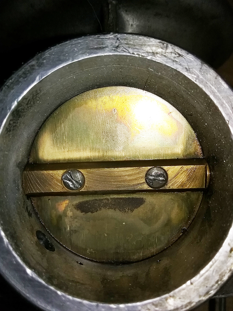
Now you remove the throttle valve disc. In theory,
this should be simple. It's held in with two screws. They're peened at
the factory - hammered on the back so they can't come loose and get
sucked into the engine. You have to file the peened end down or grind it
with a Dremel before removing the screws, so I did that.
Unfortunately...
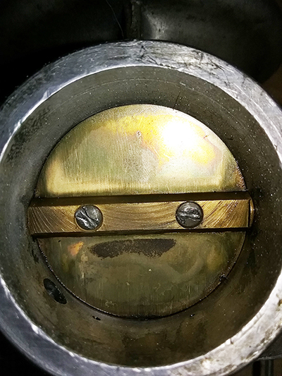
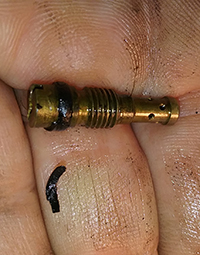
That's how I found it. Two slot-head screws that
were now hourglass-shaped. Somebody's been here before, and reused the
screws, which is doubly stupid because every rebuild kit I've seen
includes new screws. Figuring I had nothing to lose, I tried the
rubber-band-on-the-end-of-the-screwdriver trick suggested by my wife,
who's actually better at these things than me, but they weren't budging.
It was time to drag out the third most dreaded weapon in the Arsenal of
Fixing Stupid Shit: The EZ Out. (If you're wondering, the first two
are
the Helicoil and the tap-and-die set).
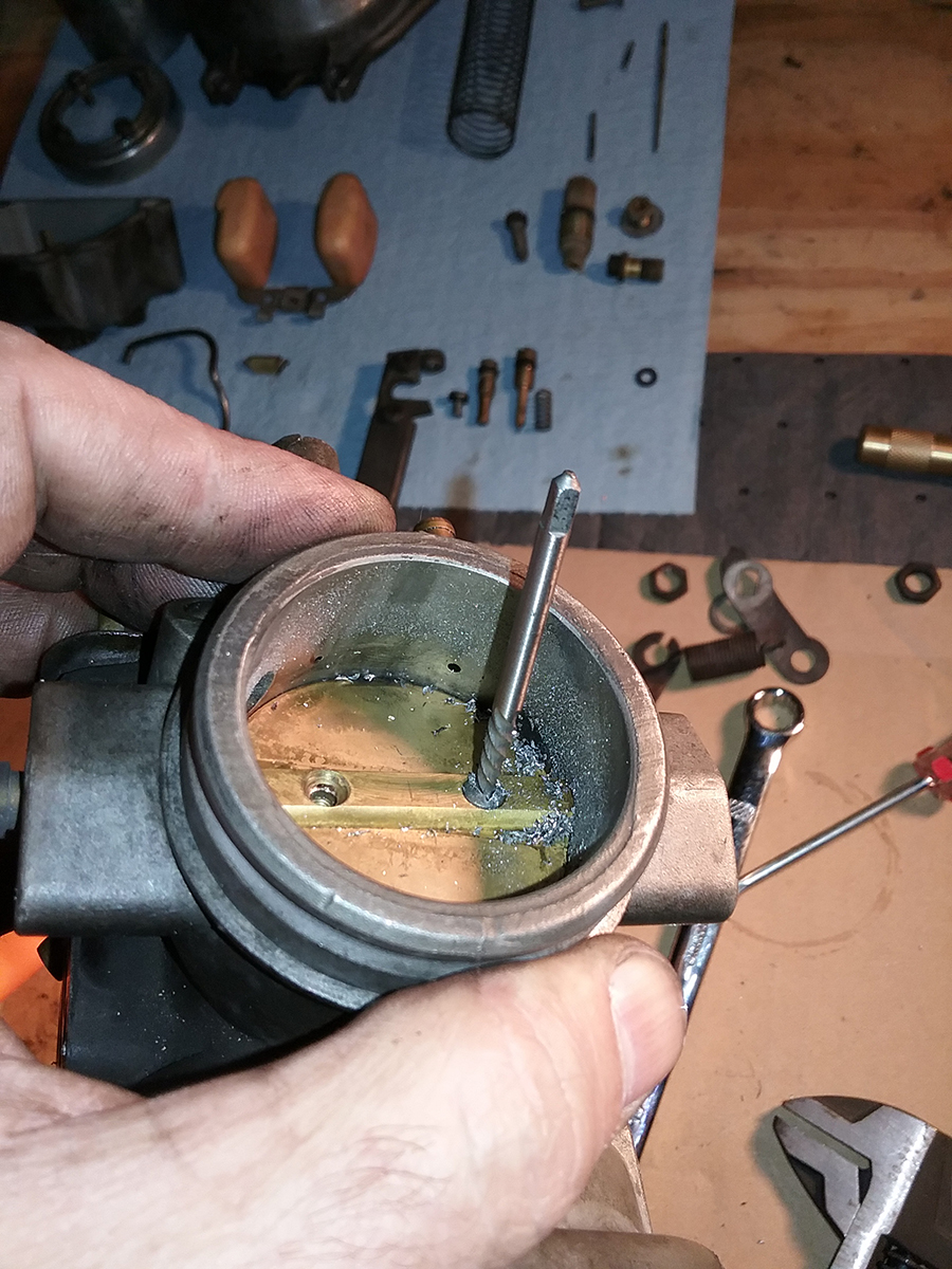
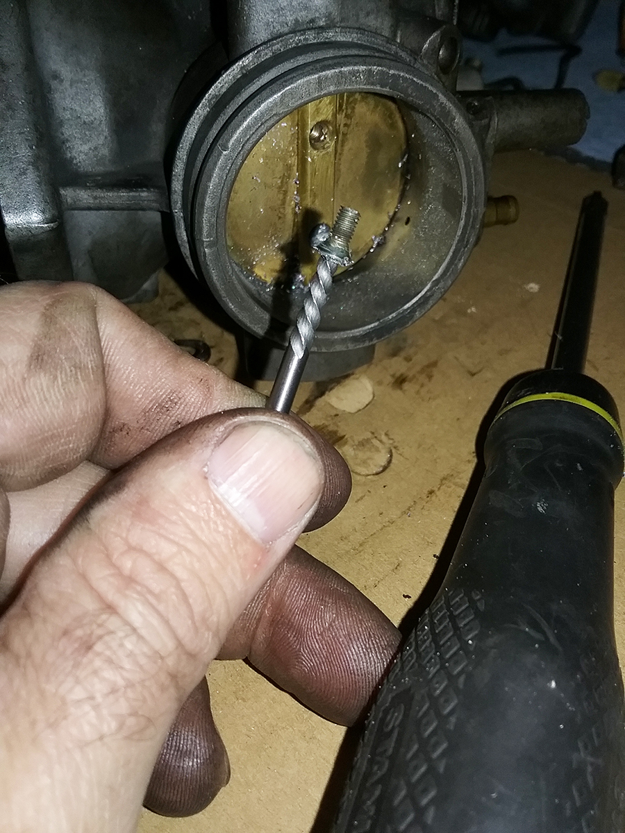
EZ Outs, or more generically, "screw extractors,"
are neither "easy" nor guaranteed to "out," but it's the last resort
short of drilling the fastener completely out and probably ruining whatever part
you're working on. The trick with these things is to drill the right
size hole (the box often comes with a guide regarding which drill bit to
use for which extractor) and go carefully. It is entirely possible to
break the hardened steel extractor off in the screw or bolt - ask me how
I know!
This particular job was made more difficult
because those screws are SMALL. Like really, really small. A slip of the bit
or drilling it off-center, and I'm looking at buying a new throttle
shaft, disc or both.
The procedure went like this:
- Use a spring-loaded punch to make a dimple in
the center of the screw head so the drill bit does not walk.
- Drill a very small pilot hole.
- Drill a larger hole with the correct bit size for
the extractor.
- Use a small hammer and gently tap the
extractor into the hole so that it bites into the metal.
- Use a wrench to turn the extractor
counter-clockwise, and ideally the screw will come with it
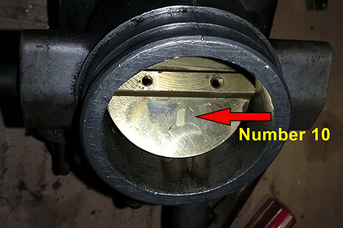
With the screws out, you can twist the throttle
shaft 90 degrees and slide the disc out. BUT WAIT, THERE'S MORE...
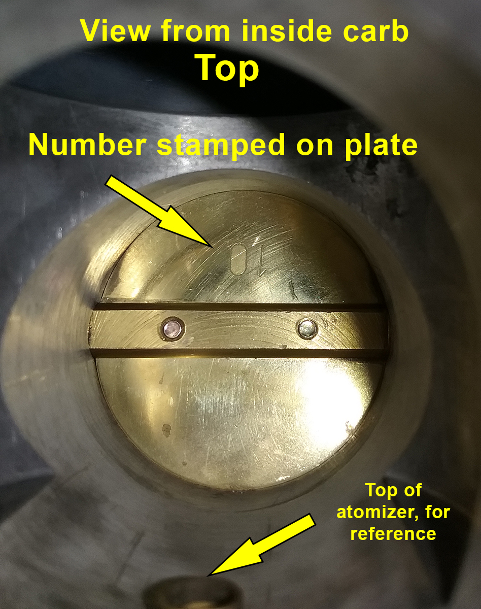
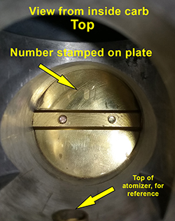
The video makes it clear, but I need to remind
you: that disc is beveled and only fits one way. Early carbs have a
dimple; later ones like this one have a number. Note the position of the dimple or
number, or score the disc yourself and make a note of where it is in
relation to the carb. If yours has a number, that will go inside, at 12
o'clock. Older carbs have dimples punched into them. Make sure you know
where they go!
Once you pull the disc out, you can remove the
throttle shaft and Demolition Day is pretty much done. Here they are.
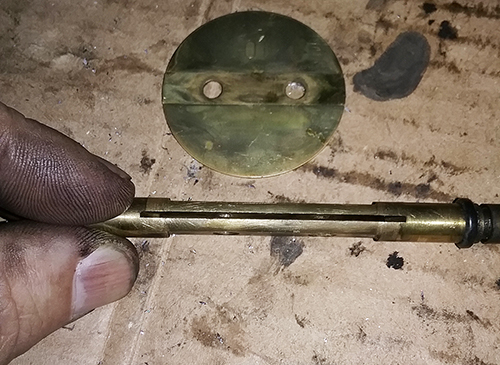
Remove any o-rings or gaskets that may still be
attached and lay everything out as neatly as you can. Here's the whole
thing, in pieces.

Step 3: Clean everything
That was easy, right? Now comes time to clean
everything up, and since the interwebs love a good argument, there are
infinite opinions regarding what to use and how to go about cleaning a
carb. Everyone is utterly convinced that, as with which engine oil to
use or the correct way to clean and lube a motorcycle chain, their way
is the very bestest and perhaps ONLY right, true and proper way and
anyone who uses some other way is an apostate who is obviously "a idiot"
and knows nothing about anything.
Here are a few of the better options:
- Ultrasonic cleaning. Unfortunately, this
requires that you either shell out $500 or more for a large enough
machine to swallow a whole carburetor, or pay someone to do it for
you.
- Vapor blasting. Again, if you have the $$$,
have at it. Not sure how well it will clean all of the small
passageways, but knock yourself out if you want.
- Put the parts in the dishwasher and run it
through a few cycles, without detergent. I really like this one! My
wife does not. Your partner may not like it either. They just don't
understand.
- Pine Sol soak. Seriously, people fill a
bucket with Pine Sol, sometimes cut with water, and they swear by
it. I gave it serious consideration, on accounta it would give the
garage that fresh pine scent.
In the end, I went for a very traditional method, recommended
by the Bing Agency video - old-fashioned carb dip.

Pretty simple. Scrub off as much crud as you can
with spray cleaner and a brush (toothbrushes or cheap plastic
brushes bought in bulk from Harbor Freight), then put the parts in the basket and
let 'em soak for a couple of hours (some people leave them in longer,
but the instructions on the can say two hours for aluminium parts, so
that's what I went with). After that, pull the basket out and rinse
thoroughly. I dunked the basket in a 5-gallon bucket of water to rinse
everything - be careful that you don't lose small parts like the jets!
After rinsing, you may need to do some scrubbing, another dipping, or
blasting everything with carb cleaner spray. In fact, it's a good idea
to use carb spray for the small passages in the carb body just for
kicks. A nice cuppa helps, and mixes well with excess carb cleaner
overspray.

When you're satisfied that everything is cleaned
and rinsed, blow everything dry with
compressed air. Be sure to get all of the passageways and small holes in
all of the parts!
When you're done, you'll see this.
Just kidding. That's from
THIS GUY'S SITE. It's an exceptionally good resource. He goes
through a complete carb rebuild as well as a lot of other stuff
elsewhere on the
site, and he
goes into greater detail, but YOU SHOULD REALLY GET THE VIDEO because it's even
better. He also used aluminium cleaner and polish and while it looks
awesome, I do not have
the time, patience or inclination for such things. So here's what I
actually ended up with.
Yes, there are still dark spots and splotches, and
I actually took a polishing wheel to small patches as a test and a wire
brush to the screws, but those metal parts are stained deeply.
Functionally, it wouldn't make a difference and they're clean enough I'd
eat off of 'em, so different strokes, folks. I think that if I had to do
it over again, I might spring for ultrasonic cleaning, but for a first
go, I'm happy.
Step 4: Put it back together
The video will give you the details, but again, I'm going
to hit the highlights and potential pitfalls (learned the hard way so
you don't have to) that are not on the
tutorial.
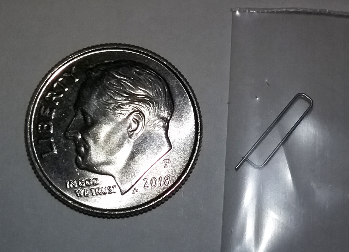
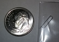
The first job is to put all of the new o-rings on
their respective parts, then it's time to hang the float needle and get
that back in place. The clip is incredibly small, so don't lose it!
Assembly is like this:
| 1. Put clip on the
needle and hang it from the tab
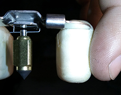 |
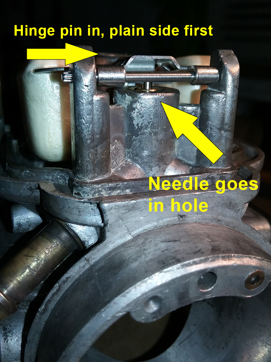
2. Drop float into place so
needle goes in the hole, insert hinge pin and tap in gently
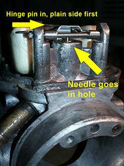 |
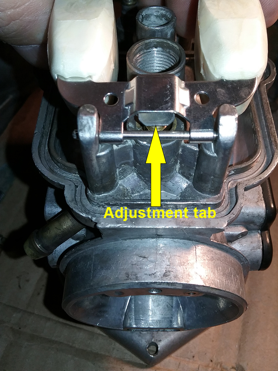
3. Top view with
adjustment tab
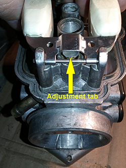 |
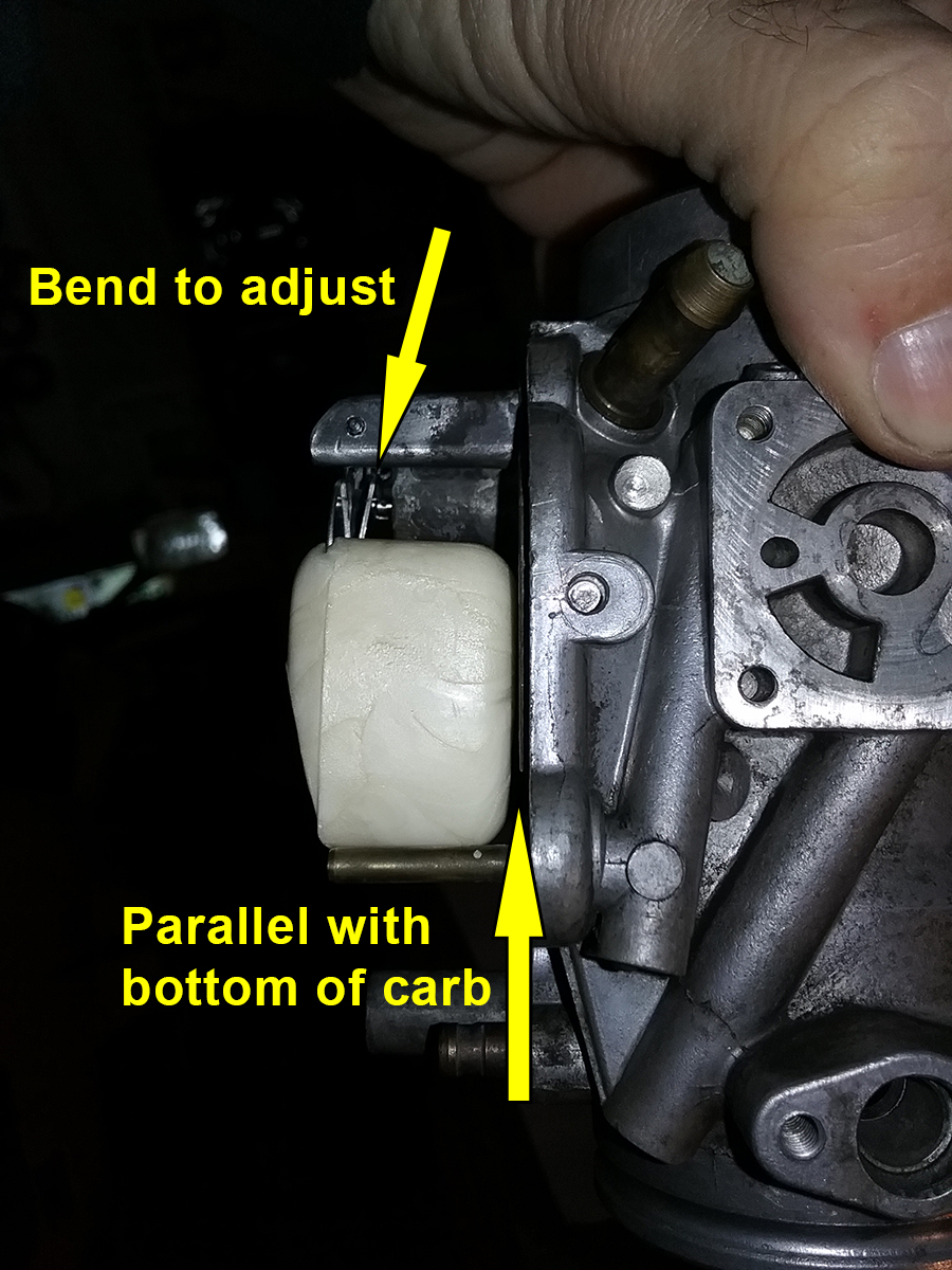
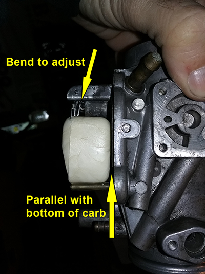
Once it's on, you need to adjust the float height.
That's important, remember? Adjustment is caveman stuff - you bend the
tab that you hung the needle from so that when the needle just touches
its seat, the floats are parallel with the bottom of the carb. Note: do
NOT adjust it so that the float is parallel when you push it all the way
down into the hole. Just when you feel it touch. An easy way to gauge is
to hold the carb 45 degrees sideways and then rotate it until the needle
touches. If the float is parallel, yay. If not, bend in the appropriate
direction. If you're really OCD, you can do this again once everything's
back together by measuring the height of fuel in the float bowl, but
this worked for me.
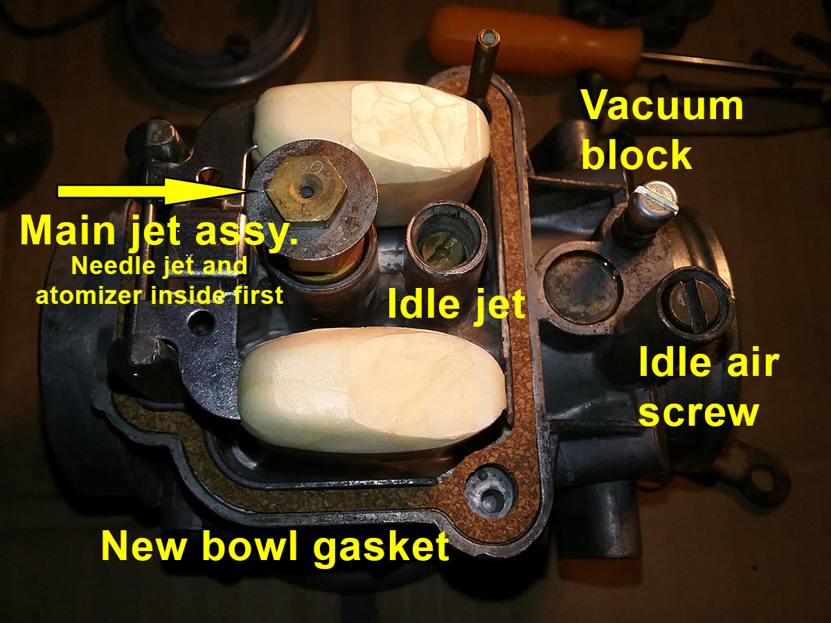
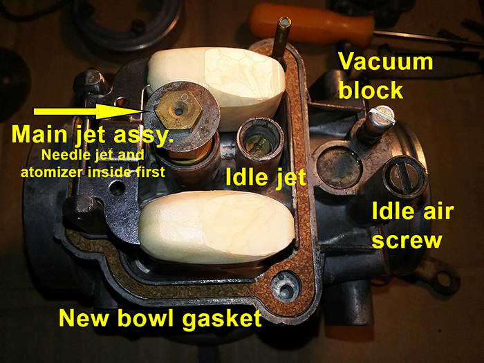
Next up, replace the jets and idle air screw with their new o-rings.
First, drop the needle jet and atomizer into the hole - make sure
they're seated properly!. Then install the main jet holder, washer and
main jet, followed by the idle jet and the idle air screw, and the
vacuum port blocking screw. All get screwed down moderately tight - as
the video notes, none of these have to be tightened too hard, but firm
enough to not come loose (ask me how I know). Note on
the idle air screw: once it's all the way in, back it out the correct
number of turns as prescribed for your carb in the carb reference chart.
You printed that, right? If not, do that now, then adjust the idle air
screw appropriately. Mine required 1.25 turns out. Here is everything installed, with a new bowl gasket.
Once that's together, you're done with the bottom!
Put the float bowl on and clip it shut with the bail.
Now we'll work our way up to the sides, easy side
first - that's the choke. It's two pieces. Put the new o-ring on,
assemble the choke, and put it on with a new gasket, using the four
screws, then attach the two-piece arm with the nut, making sure the disc
is pointing the right way.
1. Here are the two pieces that make up the choke assembly, before cleanup. |
2.
Turn the disc so the dimple on the shaft is pointing toward the air inlet of the carb (same as the hump on the choke housing), put the two parts of the arm on and secure with the brass nut. |
3. A better shot of the dimple, and
the orientation of the to arm pieces. The slotted arm with the
hole for the spring on the other side goes on so the slot faces
down. |
Next, insert the throttle shaft (with it's new
o-ring!) into the carb, then slide the throttle bracket into the groove
on the shaft and tighten the bracket down. Bing recommends Loctite on
these screws, and you'll note I've replaced the tapered-head screws with
proper flat screws.
Now for the second trickiest part after getting
the float height adjusted - installing the throttle disc. Watch the
video!
Short version: slide the disc into the slot so it
is oriented properly, align it, tighten it, secure it with Loctite or
peening.
Remember, the disc is beveled so it will only work
properly if installed correctly!
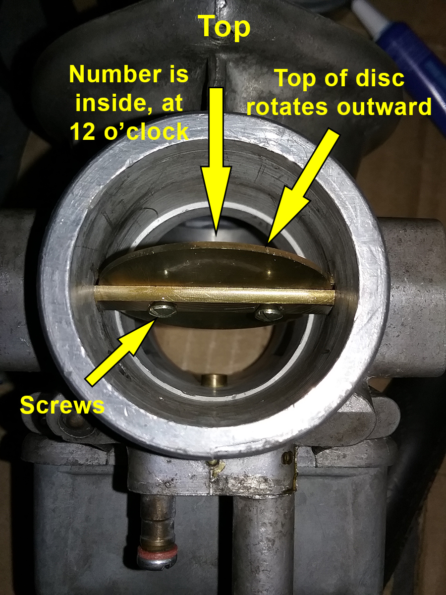
Here's how it is oriented.
| Orientation
1. The number goes on the INSIDE, at 12
o'clock. At right is the view from outside. Below is a shot from
inside.
2. The top of the disc should rotate
outward, NOT the bottom. How do I know? Because I did the first
one perfectly, got sloppy and did the second one wrong, peening the screws before I realized my mistake and had to do it
all over again once the profanities subsided. |
 |
Install the screws loosely and align the disc so
that it is centered when the throttle is closed. As noted in the video,
the top and bottom of the disc should pretty much touch, or as close to
it as you can get. Once it's aligned, tighten the screws and secure them.
There is some spirited interweb debate regarding
exactly how to secure these screws, because there is nothing that can't
be debate spiritedly on the interwebs.
As previously noted, they are peened on the
back at the factory so that they do not come loose and get sucked into
the engine. Everyone agrees that loose screws in the intake are a Bad Thing. But they disagree on
what to do when rebuilding. Some say a bit of Loctite is sufficient.
Some say you must peen the ends, and that's what the Bing Agency video
suggests. He uses a hammer and punch, supporting the shaft on a piece of
wood in a vice so you do not bend it. Seriously: do not bend the
throttle shaft!
I used same the piece-of-wood-in-a-vice method, but
because I was so busy admiring the cleverness of this trick, I forgot to
take a picture of the setup. Watch the video! Also, instead of a hammer
and punch, I used a spring-loaded punch placed off-center near the edge,
to peen the end of the screw. Worked for me. Your mileage may vary, etc.
Once that's done, install the two-piece control
arm assembly, return spring, and idle adjusting screw.
Now, pre-set the idle speed by turning the
adjustment screw one full turn further from when it first contacts the
tab on the control arm.
Now we move on to the top of the carb. First, assemble the slide
and needle.
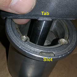
1. Align the tab on the diaphragm
with the tab on the slide. |
2. Once aligned, insert the retainer
ring and tighten with four screws. |
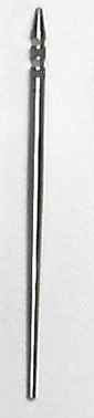
3. The needle has four slots and
is held in the slide by a spring device. Push the needle into
the correct slot (numbered 1-4, top to botttom) so it is the
correct height for your carb, as noted on the reference chart.
For each slot, rotate the needle 90 degrees and push again. Mine
went in the second slot |
If I had it to do over again, I would have bought
new needles and needle jets as well. One of them was shiny and
unmolested, while the other had signs of wear. Again, someone has been
here before.
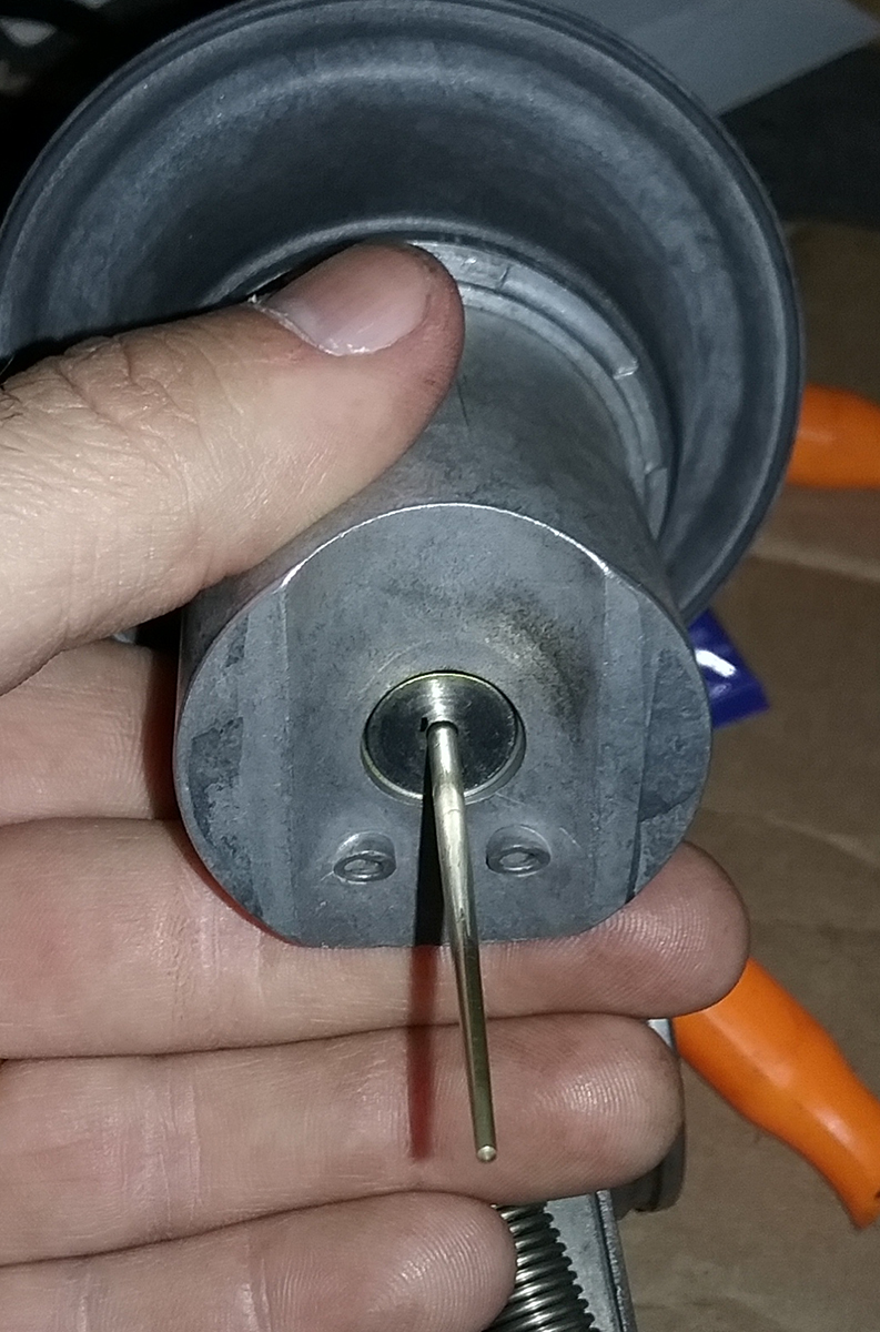
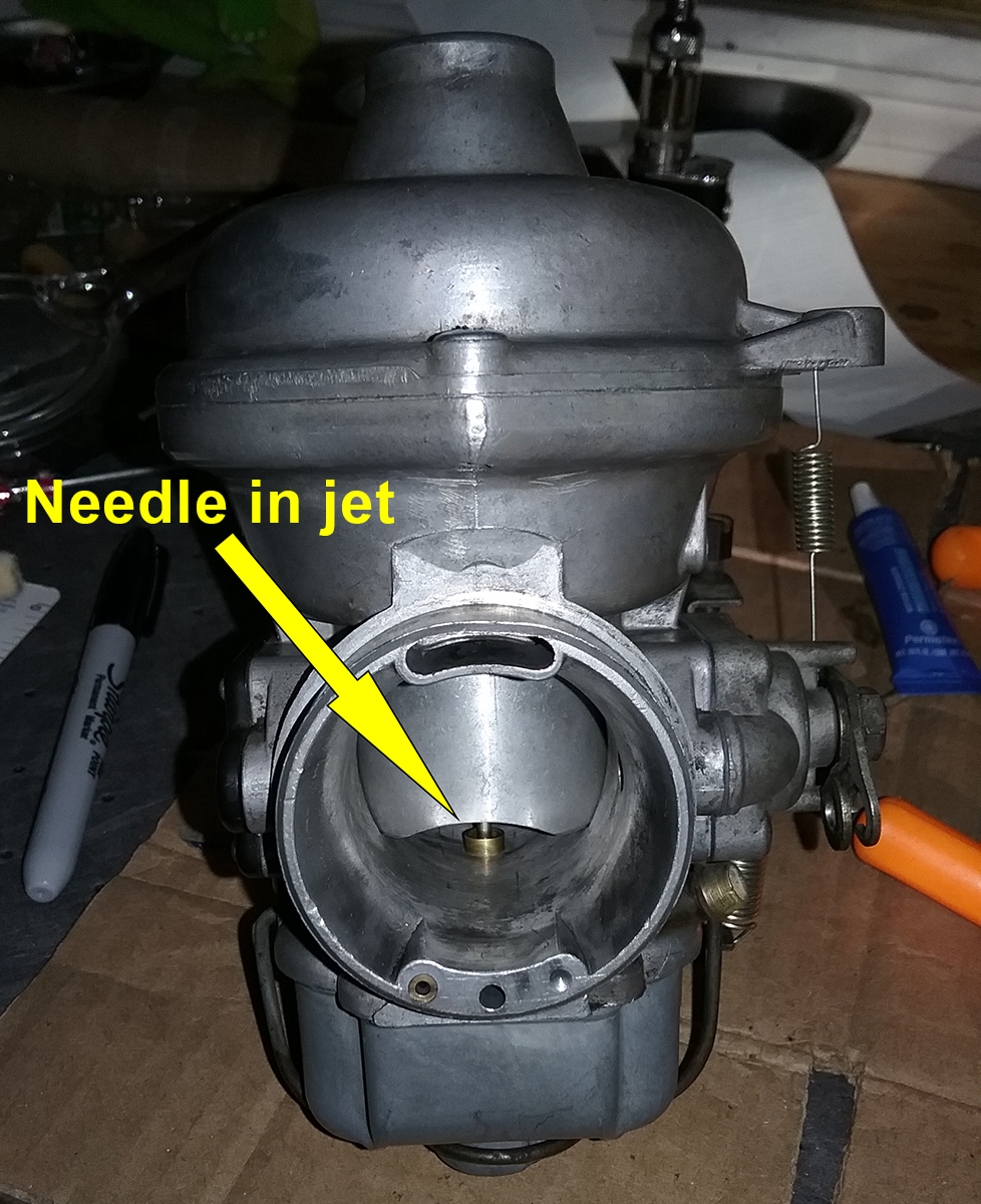
Regardless, once assembled, put the slide into the carb body,
being careful to align the needle so it goes into the jet hole.
There is
another tab on the outside of the diaphragm that goes in a slot in the
top of the carb body. Align those and the slide will be correctly
oriented, then pop the top on.
I used new carb top screws. Since these are prone
to seizing, use some anti-sieze on the threads so that the next time you
or someone else needs to take it apart, the amount of profanities will be
limited.
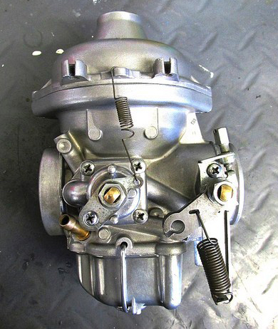
Here is the slide in place. The rebuild is
finished, but not the story - they still have to go back on and be
adjusted.

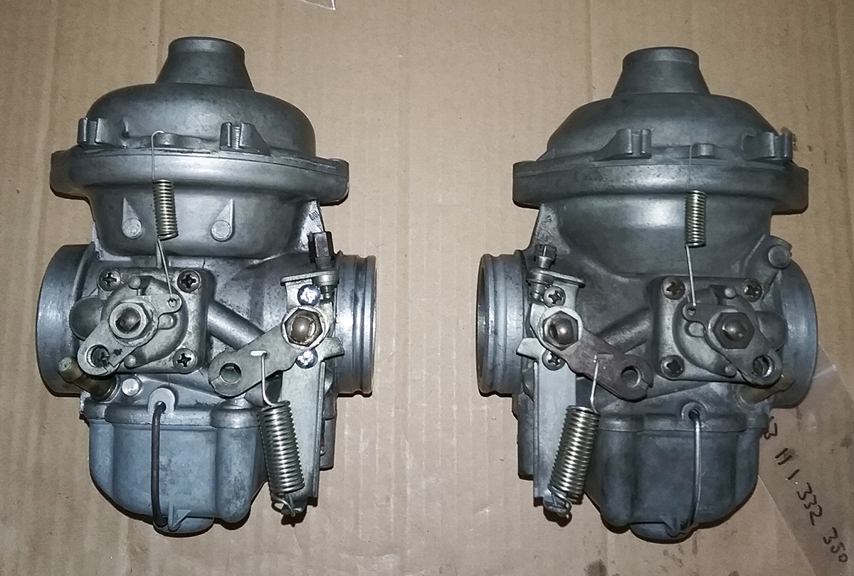
Here's the pair done and ready to go back on the
bike. Little did I know, it would be another week before the project
would be through, because (cue Fixx song!).
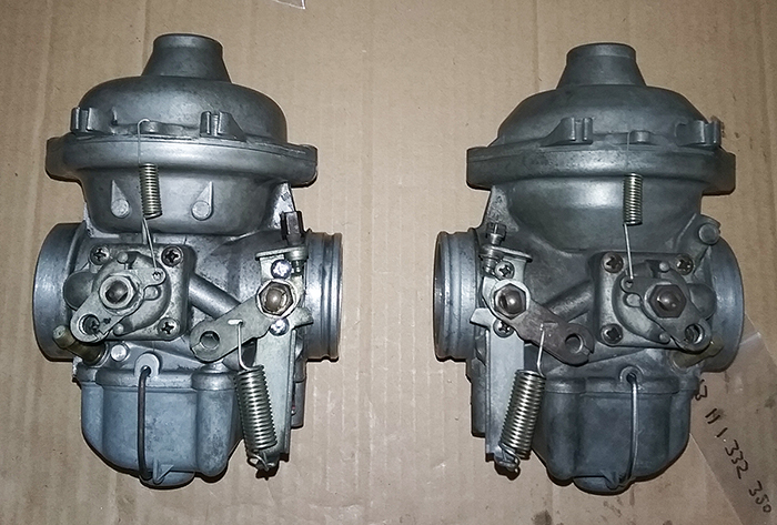
One thing to note: Yes, Hawkeye, the carbs are probably from
different motorbikes and you'll see some subtle differences, most
notably that the top of the left one is rounded, while the right one is
angled. When I bought the thing back around the turn of the millenium,
it came with "spare parts" including carb bodies, but this was what was
on there. Most importantly, the numbers stamped on each is correct for
the model and year of the bike. And while they are clean, they are not
sparkly. Next time, I'll find someone with a vapor blaster or ultrasonic
cleaner.
Step 5: Put 'em back on the bike
This should be a cake walk: Hook up cables, attach
carbs between airbox and cylinder head, connect fuel line, fiddle with
a few adjustments and ride off into the sunset.
But it wasn't. Once again, the Ghost of Owners
Past haunted me.
It started easily enough, as all carburetor
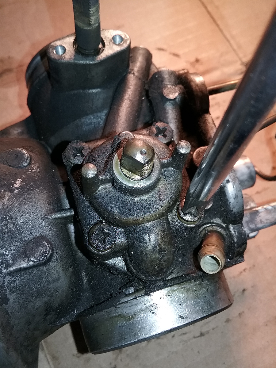
installations do - by adjusting the valves.
That's right. Valve clearance can have a
significant effect on how the motorbike idles and runs, especially on
old airheads. In fact, what is often thought to be a carburetor issue
can be cured by a valve adjustment. So the first step was to do
that. Since it involves screws and locknuts, it's fairly easy compared
to setups that use shims. The Clymer and Haynes manuals have
straightforward instructions, and there are plenty of YouTube how-tos,
although I'll probably do my own tutorial on it one of these days
just because. Meanwhile, here's what that assembly looks like.
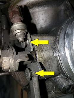
With that complete, I went to put the first
carburettor back on the bike and, while attempting to attach the
throttle and choke cables, immediately noticed a problem. Even with
every adjustment made to ensure maximum length, the cable was too short.
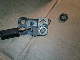
In the photo below, the top arrow shows the adjuster and the bottom
arrow shows a gap between the control arm and the stop that it is
supposed to rest on. The arm should sit on the stop AND there should be
some slack in the cable. And before anyone asks, yes, I know there is
another adjuster further up the line and I fiddled with that one too,
but this was as far as I could go. This would also explain why the left
spark plug always read rich since I've owned the thing.
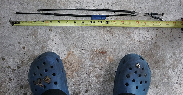
To find out why this was happening would require pulling all of the
cables. For complete details on the process,
the esteemed Brook Reems has an excellent tutorial that I used for
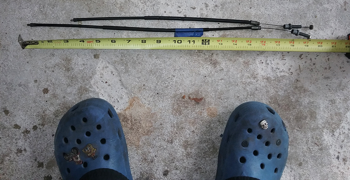
reference and can't really add to. Once the cables were off, I measured
the throttle and choke for the left carb. They should be about 20 inches
long. Surprise! Not even close. Some moron had used the wrong cables. And yes Crocs with socks are acceptable
fettling footwear in winter weather.
Cursing the previous knucklehead who had worked on
this bike, I pulled the cables from the
other side and, while they were right, they were worn, so figured I might as well replace everything.
Because "German
Engineering," that meant six cables.
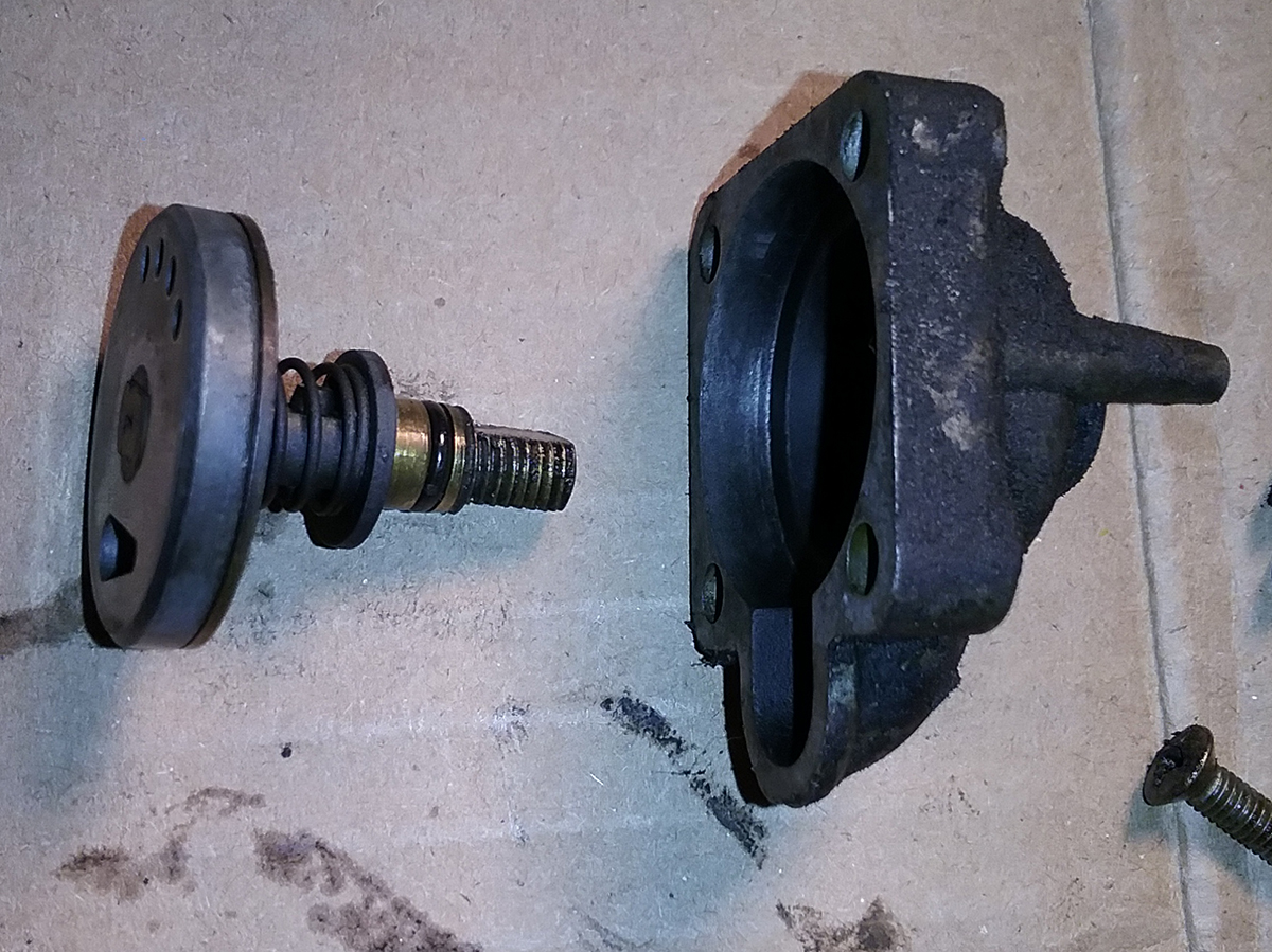
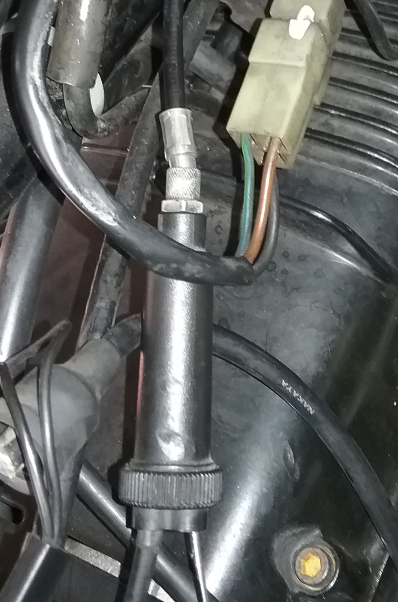
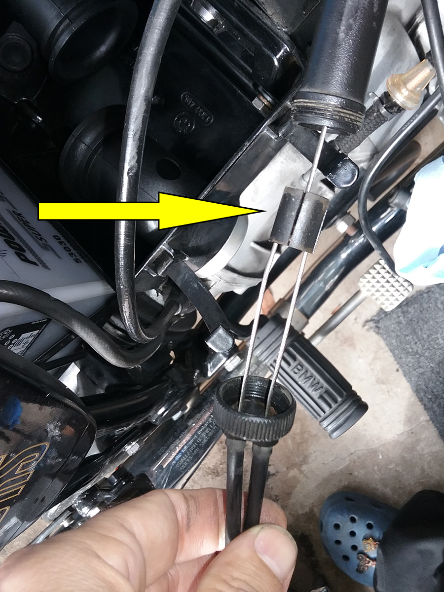
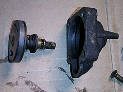
For each function - choke and throttle - there is a primary cable that
runs from the handlebar controls. That goes into one end of a "Bowden
connector" and attaches to a sliding cylindrical block inside, to which the
cables from the carbs are also attached, thereby allowing you to pull the two
cables using the one that's attached at the handlebar. Below are photos
showing the connector together and apart, with the arrow pointing out
the sliding block.
After a week of waiting for the new cables to
arrive, I assembled everything with new carb boots, cables, fuel line,
air filter, plug wires and spark plugs and got down to the business of tuning.
Sure, tuning is sort of voodoo. I've seen shamans
who can determine fuel mixture by scent and timing by ear. But on the
Bings, it comes down to a few basics, all measurable with simple
scientific
instruments, no third eye or sixth sense required:
- Jetting, which we don't have to worry about
because everything's stock.
- Balance at idle, which means ensuring both
carbs are getting equal and optimal air-fuel mixture at idle with
the throttle closed.
- Synchronization, which means both throttles
are opening and closing at the same time, at the same rate, so one
cylinder doesn't try to outpace the other. That would be a Bad
Thing.
With stock jets, the first thing we really need to
worry about is balance, which on the Bings means idle air mixture
because that's the only thing available.
Remember, the idle jet is one size, and the only adjustment is the idle
air screw. That was pre-adjusted 1.25 turns out from full stop. We'll
fine-tune it later once the engine is fully warmed up.
Synchronization is a little tricker and also
requires the bike to be fully warm, but it starts by adjusting the slack
in the throttle and choke cables using the knurled adjuster at the top
of the carb, and setting it firmly with the lock nut. Ideally, you'll
screw it in about halfway along the adjuster thread so you have room for
future fiddling as cables stretch and wear.
Make sure all of the cables are properly seated at
the handlebar control, the Bowden connector and the carbs. This can take
a while - there are adjusters on the Bowden connectors as well and there
are 12 points of contact that have to be solid. Work the throttle and
choke levers and get everything well-seated. Once you're satisfied,
adjust at the carb so you have about 1-2mm of slack in each cable before
the lever budges, as shown in this annoying animated GIF I made. The
important thing is that all cables have an equal amount.
Caveat: I've seen recommendations from 1mm to 4mm
for cable slack, and because we now have the interwebs, the subject is a
wellspring of fierce sturm und drang, with everyone claiming
biblical inerrancy and offering reasons from complex engineering
explanations to "it feels right."
The bottom line is twofold:
1. You gotta have slack so that the throttle and
choke will close to their stops at idle.
2. That slack has to be equal so that everything
opens up at the same time, and therefore evenly.
Once all of your basic settings are done, it's
time to start it up and go for a ride. Most recommend about 20 minutes
to fully warm up the motor. I made it about three and a half before I
knew something was seriously wrong.
While the motorbike started and idled fine, within
a mile it was running rough and idling erratically, dangerously even, so
it was back to World Headquarters to figure out what was wrong.
My first hunch was that the new cables may have
been routed wrong and were binding, so I made sure everything was moving
freely. Another ride confirmed that this hadn't solved the problem. A
call to the Bing Agency got a recommendation to check the throttle plate
alignment, which required the carbs to come off again. The first step to
that, of course, is to drain the float bowls, and as soon as I pulled
the left one off, I found the problem: the main jet had come loose from
its holder and was wobbling in its brass threads. I know I tightened the
thing, but apparently not enough. I corrected that issue, checked the
throttle plates (they were fine, thank you) put everything back together
and went for another ride.
The second test run was a world apart from the
first, with the only issue being that it was idling at 4,000 rpm. A few
seconds adjusting the throttle stop/idle speed screws (evenly, a little
at a time) had it ticking along at 1,250 and since it was fully warm,
balance and synch were in order.
That is a whole, 'nother tutorial, but the short
version is that
in my case, no adjustment was necessary to the idle air screws, and very
little cable adjustment was needed to sync, though I will have to check
it once the new cables have had their initial stretch.
Without going into an entire tutorial about
balance and sync, I will say that once again, there is a monumentally
wide variety and rabid intensity of opinion regarding the best method.
Many, many airhead afficionados use the "shorting the plugs" method (you
can google it), but many, many people have also destroyed their pricey
electronic ignition doing so. If you have an old airhead with points,
knock yourself out with the screwdriver and have fun with the sparks.
Seriously, everyone loves sparks.
But if you have one with an electronic ignition,
please do something else. I have dial gauges and even an old-school,
incredibly toxic mercury manometer, and I've used them on triples and
four-cylinder bikes. The
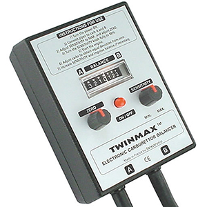
Bing Agency has several options you might consider. But for the airhead, I like the
Twinmax. It's butt-simple and while you can always find some Haters,
the thing works for me and lots of others.
Once tuned, the old airhead ran like a completely
different bike, better in every way. It was a joy rather than a chore
and I rode high on a wave of fettling satisfaction for an entire day
until, coming back from work, I rounded a corner a block from home and
tried to shift, but instead of the usual mechanical clunk, there was
nothing. No up. No down. Stuck in gear. It is the nightmare every airhead
rider hopes never comes true: The pawl spring, a $3 part inside the
transmission, had broken. To fix it requires four to six hours of shop
labor, because the transmission has to be removed and opened up,
requiring special tools and even more special knowledge. Because one
thing always leads to another.

Return home |